Last Updated: October 2025 | Reading Time: 22 minutes | Expert Guide by CalibVision
What is a Camera Calibration Target?
Quick Definition
Camera Calibration Target: A precision-manufactured plate featuring accurately positioned patterns (checkerboard, dots, circles, or coded markers) printed on rigid substrates like glass or ceramic. These targets enable machine vision cameras to correct lens distortion, establish accurate measurements, and determine the geometric relationship between 3D world coordinates and 2D image pixels. Typical accuracy ranges from ±1 micron (glass) to ±5 microns (aluminum composite).
Why Camera Calibration Matters
In machine vision, robotics, photogrammetry, and 3D reconstruction, camera calibration is the foundation of accurate measurement. Without proper calibration:
Measurement errors can reach 10-50% of actual dimensions
Lens distortion creates curved lines where straight edges exist
3D reconstruction produces warped or inaccurate models
Robot positioning fails due to incorrect spatial relationships
Quality inspection systems generate false positives or miss defects
A calibration target provides the known geometric reference that allows calibration algorithms to:
- Calculate intrinsic parameters (focal length, principal point, lens distortion coefficients)
- Determine extrinsic parameters (camera position and orientation in 3D space)
- Establish pixel-to-world coordinate transformation
- Correct radial and tangential distortion from lenses
- Enable accurate dimensional measurements in real-world units
The Calibration Process Overview
Camera calibration involves capturing multiple images of a calibration target from different positions and angles. Software algorithms analyze these images to:
- Detect pattern features (corners, circles, or coded markers)
- Establish correspondences between 2D image points and known 3D positions
- Calculate camera parameters through mathematical optimization
- Generate calibration matrices for image correction and measurement
Critical Insight: The accuracy of your calibration is fundamentally limited by the accuracy of your calibration target. A target with ±10 micron feature positioning can never achieve ±1 micron measurement accuracy in your system.
How Camera Calibration Works
The Pinhole Camera Model
Most camera calibration is based on the pinhole camera model, which describes how 3D points in the world map to 2D points in an image:
Mathematical Representation:
s * [u, v, 1]ᵀ = K * [R | t] * [X, Y, Z, 1]ᵀ
Where:
- (u, v) = 2D image coordinates (pixels)
- (X, Y, Z) = 3D world coordinates (millimeters)
- K = Intrinsic matrix (camera internal parameters)
- [R | t] = Extrinsic matrix (rotation and translation)
- s = Scaling factor
Intrinsic Parameters
Intrinsic parameters describe the camera’s internal optical characteristics:
| Parameter | Description | Impact |
|---|---|---|
| fx, fy | Focal lengths in x and y directions (pixels) | Image magnification |
| cx, cy | Principal point (optical center, pixels) | Image center offset |
| k1, k2, k3 | Radial distortion coefficients | Barrel/pincushion distortion |
| p1, p2 | Tangential distortion coefficients | Lens decentering effects |
Real-World Impact: A consumer-grade lens might have k1 = -0.3, causing 5-10% distortion at image edges. Industrial lenses with k1 < 0.05 minimize this effect but cost 10-20× more.
Extrinsic Parameters
Extrinsic parameters define the camera’s position and orientation in 3D space:
- Rotation matrix (R): 3×3 matrix describing camera orientation
- Translation vector (t): 3×1 vector describing camera position
These parameters change every time the camera moves, while intrinsic parameters remain constant for a given lens/sensor combination.
Lens Distortion Types
Radial Distortion (most significant):
- Barrel distortion: Image appears bulged (k1 < 0)
- Pincushion distortion: Image appears pinched (k1 > 0)
- Caused by light rays bending more at lens edges
Tangential Distortion:
- Occurs when lens elements aren’t perfectly aligned
- Causes image plane to be non-parallel to lens plane
- Generally smaller magnitude than radial distortion
Why This Matters: Wide-angle and fisheye lenses (>90° FOV) require special calibration models accounting for severe barrel distortion. Standard calibration fails beyond 120° FOV.
The Role of Calibration Targets
Calibration targets provide ground truth — known geometric patterns with precisely measured dimensions. By capturing these patterns from multiple viewpoints:
- Feature extraction algorithms locate corners, circle centers, or coded markers
- Correspondence establishment matches 2D image features to 3D target coordinates
- Optimization algorithms minimize reprojection error to compute camera parameters
Accuracy Relationship:
Final Measurement Accuracy ≈ Target Accuracy × sqrt(N) / Calibration Images
More calibration images improve accuracy, but target precision sets the fundamental limit.
Types of Calibration Patterns Explained
Pattern Selection Quick Reference
| Pattern Type | Detection Ease | Occlusion Robustness | Stereo Compatible | Best Use Case |
|---|---|---|---|---|
| Checkerboard | ⭐⭐⭐⭐⭐ | ⭐ | ✅ (asymmetric) | General calibration, OpenCV |
| Circle Grid (Symmetric) | ⭐⭐⭐⭐ | ⭐⭐ | ❌ | Thermal cameras |
| Circle Grid (Asymmetric) | ⭐⭐⭐⭐ | ⭐⭐ | ✅ | Robust detection |
| CharUco Board | ⭐⭐⭐⭐ | ⭐⭐⭐⭐⭐ | ✅ | Partial occlusion scenarios |
| AprilGrid | ⭐⭐⭐ | ⭐⭐⭐⭐⭐ | ✅ | Robotics, multi-sensor |
| Dot Grid | ⭐⭐⭐ | ⭐⭐ | ✅ | High-precision metrology |
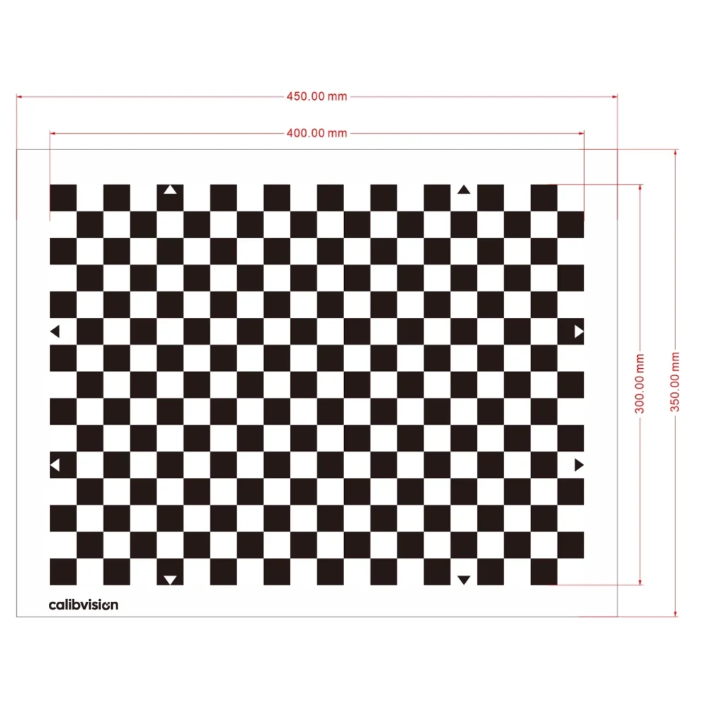
1. Checkerboard / Chessboard Pattern
Description: Alternating black and white squares forming a grid pattern, similar to a chess board.
Technical Specifications:
- Corner detection at square intersections
- Typical sizes: 7×7 to 13×15 grid
- Square size: 0.5mm to 50mm depending on application
- Sub-pixel corner detection accuracy: ±0.1 pixels
Advantages:
✅ Universally supported — OpenCV, MATLAB, Halcon, ROS all have built-in detection
✅ Easy to manufacture with high contrast
✅ Fast detection algorithms (goodFeaturesToTrack, findChessboardCorners)
✅ Sub-pixel accuracy achievable through corner refinement
✅ Cost-effective production on various substrates
Disadvantages:
❌ Full visibility required — Any occlusion breaks detection
❌ Lighting sensitive — Reflections can obscure corners
❌ 180° ambiguity with symmetric patterns (stereo calibration issue)
❌ Flat surface essential — Any warping affects accuracy
Best Applications:
- Single camera calibration (industrial inspection, measurement)
- Laboratory calibration stations
- Educational and research projects
- OpenCV-based systems (most popular choice)
CalibVision Products:
- OpenCV Checkerboard Series (Glass & Ceramic, 2mm-8mm square sizes)
- Halcon Compatible Series (7×7 dot array with precise positioning)
2. Circle Grid Pattern
Description: Evenly spaced circles arranged in a grid. Two variants: symmetric (aligned rows/columns) and asymmetric (offset pattern).
Symmetric Circle Grid:
- Circles aligned in perfect rows and columns
- Center-to-center spacing precisely controlled
- Circle diameter: 0.5mm to 20mm typical range
Asymmetric Circle Grid:
- Every other row offset by half the spacing
- Eliminates 180° ambiguity for stereo calibration
- Unique pattern orientation detection
Advantages:
- Better for thermal/IR cameras — Circles produce cleaner edges than squares
- Robust center detection — Centroid calculation less affected by noise
- Works with significant lens distortion — Circles remain detectable when distorted
- Asymmetric version resolves stereo ambiguity
Disadvantages:
- Slower detection than checkerboards
- Requires precise printing — Elliptical circles cause errors
- Less software support than checkerboards
- Symmetric version unsuitable for stereo
Best Applications:
- Thermal camera calibration (FLIR, LWIR sensors)
- Systems with extreme lens distortion (>120° FOV)
- Photogrammetry with close-range photography
- Backlight illumination systems (circles as holes)
Manufacturing Note: Glass targets can have drilled circular holes for backlight applications, providing perfect circle geometry and high contrast.
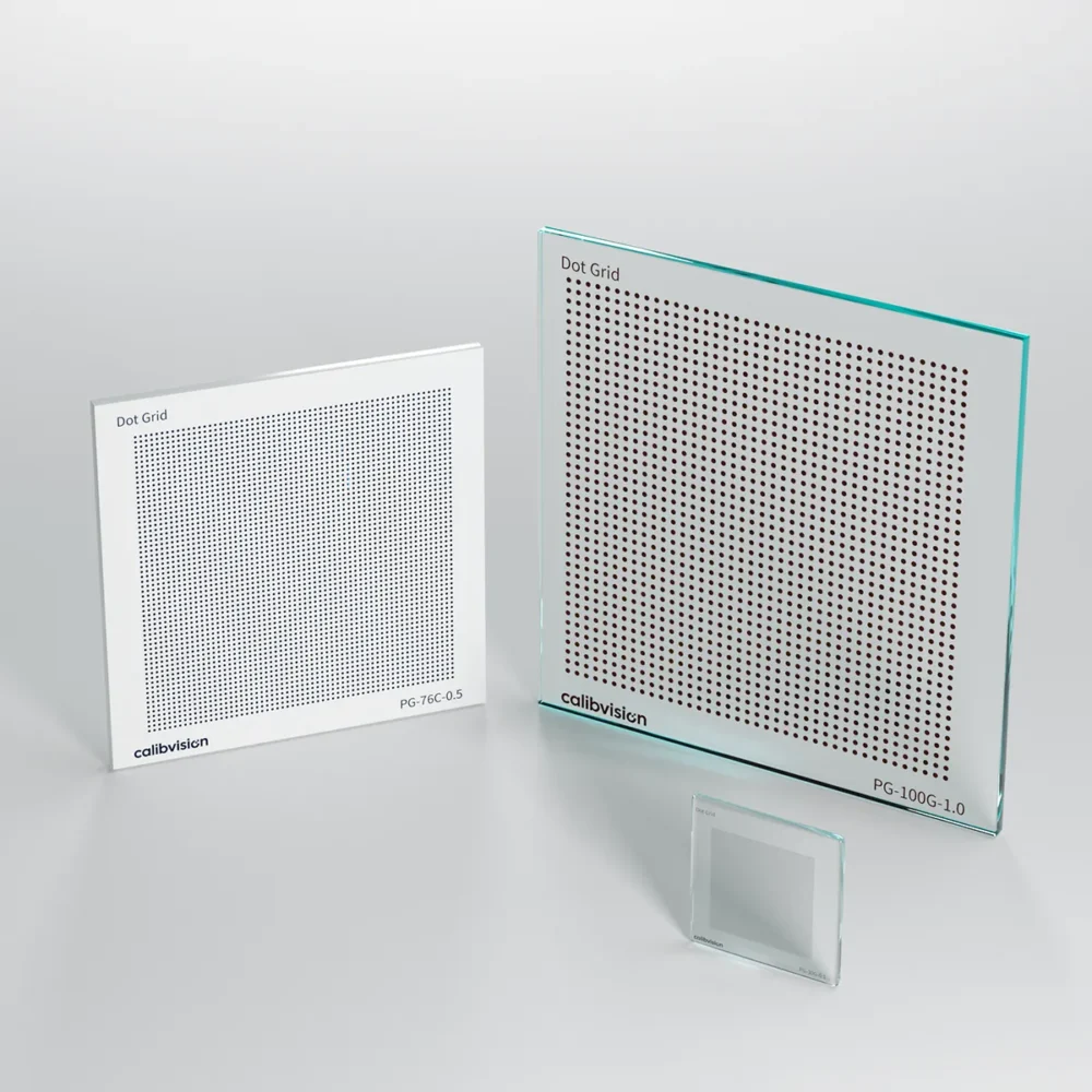
3. Dot Grid / Array Pattern
Description: Regular array of solid dots (filled circles) with precise center-to-center spacing.
Technical Specifications:
- Dot diameter: 0.1mm to 6mm
- Dot spacing: 0.2mm to 20mm
- Array sizes: up to 101×101 dots
- Position accuracy: ±1μm (glass) or ±2μm (ceramic)
Advantages:
✅ Highest precision — Dot centers can be located with 0.01-pixel accuracy
✅ Dense feature distribution — More calibration points per area
✅ Compatible with Halcon CALTAB — Industry-standard metrology software
✅ Suitable for sub-pixel measurement applications
✅ Works with both front and backlight illumination
Disadvantages:
❌ Requires specialized detection algorithms
❌ Less common in open-source tools
❌ Precision manufacturing needed — Low-quality dots cause errors
❌ May require manual point identification without coded markers
Best Applications:
- High-precision metrology and measurement systems
- Coordinate measuring machine (CMM) calibration
- Optical stage calibration (X-Y positioning)
- Microscope calibration and magnification verification
- Structured light 3D scanning systems
CalibVision Products:
- Dot Grid Series (WMD series, 0.1mm-2.0mm dot spacing)
- Compatible with MVTec Halcon dot detection algorithms
4. CharUco Board Pattern
Description: Hybrid pattern combining a checkerboard with ArUco markers embedded in the white squares.
Technical Details:
- Standard checkerboard base pattern
- Binary ArUco markers (4×4, 5×5, or 6×6 bits) in white squares
- Each marker has unique ID for identification
- Dictionary sizes: 50 to 1000 unique markers
Advantages:
✅ Partial occlusion resistant — Can calibrate even when parts are hidden
✅ Unique identification — Each corner associated with known marker ID
✅ Automatic pose estimation — Markers provide 6-DOF pose
✅ Error detection/correction — Wrong detections can be filtered out
✅ Excellent for multi-camera networks and difficult angles
Disadvantages: ❌ More complex to generate — Requires CharUco board creation tools
❌ Lower corner density — Fewer calibration points than pure checkerboard
❌ Marker detection overhead — Slightly slower processing
❌ Printing quality critical — Marker codes must be clear
Best Applications:
- Multi-camera calibration networks (surveillance, motion capture)
- Outdoor calibration where occlusions occur (trees, people)
- Augmented reality tracking and registration
- Robotic applications with dynamic environments
- Long-range calibration where targets may be partially visible
Software Support:
- OpenCV (cv2.aruco.CharucoBoard)
- MATLAB (generateCharucoBoard)
- Custom implementations in Python/C++
5. AprilGrid / AprilTag Pattern
Description: Grid of AprilTag fiducial markers, each providing 4 corner features.
Technical Specifications:
- Tag families: tag16h5, tag25h9, tag36h11 (different bit configurations)
- Each tag: 4-12mm typical size
- Grid arrangements: 4×4 to 8×10 common layouts
- Detection range: up to 50× tag size distance
Advantages:
✅ Most robust to occlusion — Each tag detectable independently
✅ Unique identification — Every tag has distinct ID
✅ Long-range detection — Readable from greater distances than corners
✅ Excellent pose estimation — 6-DOF pose per individual tag
✅ Popular in robotics — Native ROS support (Kalibr package)
Disadvantages:
❌ Lower feature density — Fewer points than checkerboards
❌ Requires sharp images — Blurred tags fail detection
❌ Printing precision critical — Binary codes must be exact
❌ Limited software support outside robotics community
Best Applications:
- Mobile robot calibration (Kalibr for ROS-based systems)
- UAV/drone camera calibration
- Multi-sensor calibration (camera + LiDAR fusion)
- SLAM systems (Simultaneous Localization and Mapping)
- Warehouse automation and AGV navigation
Kalibr Compatibility: The Kalibr calibration toolbox (ETH Zurich) specifically uses AprilGrid targets for multi-camera and camera-IMU calibration in robotics.
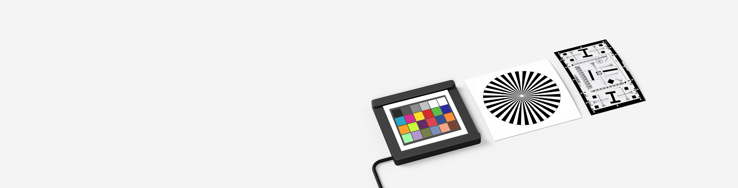
6. ISO 12233 Test Charts
Description: Standardized resolution test patterns for image quality assessment.
Pattern Elements:
- Slanted edge features for MTF measurement
- Low contrast patterns for dynamic range
- Star patterns for radial resolution
- Checkerboard patches for distortion
- Color patches for color accuracy
Key Standards:
- ISO 12233:2017 (current standard)
- ISO 12233:2014 (previous version)
- ISO 15739 (noise measurements)
- ISO 14524 (OECF measurements)
Use Cases:
✅ Camera module qualification in manufacturing
✅ Lens MTF (Modulation Transfer Function) testing
✅ Sensor resolution verification
✅ Image processing algorithm validation
✅ Quality control in camera production lines
Not Suitable For:
❌ Geometric calibration (distortion correction)
❌ 3D measurement applications
❌ Robot vision systems
CalibVision Products:
- ISO12233 Test Targets (edge-based SFR patterns)
- Available on glass with high-precision edges
7. USAF 1951 Resolution Targets
Description: Classic resolution test pattern with groups of line pairs at progressively smaller sizes.
Pattern Structure:
- Groups -2 to 9 (11 resolution levels)
- Each group: 6 elements at different orientations
- Line pair frequencies from 0.5 to 228 lp/mm
- Positive (dark lines) or Negative (light lines) versions
Technical Details:
- Group/Element notation: “Group 2, Element 4” = 5.66 lp/mm
- Optical density: >3.0 (chrome on glass) or >5.0 (blue chrome)
- Edge quality: <1μm edge roughness critical
Applications:
✅ Optical system resolution testing
✅ Microscope calibration
✅ Lens quality assessment
✅ Focus and depth-of-field analysis
✅ Sensor pixel pitch verification
CalibVision Products:
- WMU Series (Glass substrates, Groups -2 to 9)
- Positive and Negative versions available
- Blue chrome option for extended dynamic range
Calibration Target Materials Comparison
Material Selection Matrix
| Material | Accuracy | Flatness | Thermal Stability | Durability | Cost | Best For |
|---|---|---|---|---|---|---|
| Soda Lime Glass | ±1μm | Excellent | Good (8.5 ppm/°C) | Good | $$$ | Backlight, precision |
| Quartz Glass | ±0.5μm | Superior | Excellent (0.55 ppm/°C) | Excellent | $$$$ | Metrology, extreme temp |
| Ceramic (Al₂O₃) | ±2μm | Excellent | Very Good (6-8 ppm/°C) | Excellent | $$ | Frontlight, rugged |
| Aluminum Composite | ±5μm | Very Good | Good (23 ppm/°C) | Very Good | $ | Large format, portable |
| Carbon Fiber | ±3μm | Excellent | Excellent (0.5 ppm/°C) | Excellent | $$$ | Aerospace, lightweight |
Soda Lime Glass Substrates
Material Properties:
- Chemical composition: SiO₂ (70-75%), Na₂O (12-16%), CaO (9-12%)
- Thermal expansion: 8.5×10⁻⁶ /°C
- Transmission: >90% at 550nm wavelength
- Surface flatness: <5μm across 100mm
Chrome Coating Types:
Brown Chrome (Standard):
- Optical density (OD): 3.0-3.5
- Reflectivity: 6-30% (440-1040nm range)
- Appearance: Dark brown/bronze
- Best for: Visible spectrum cameras, standard machine vision
Blue Chrome (High OD):
- Optical density (OD): >5.0
- Reflectivity: <2% across visible spectrum
- Appearance: Deep blue-black
- Best for: High dynamic range sensors, precision metrology
Yellow Chrome:
- Gold/yellow appearance
- Premium aesthetic
- Similar optical properties to brown chrome
Manufacturing Process:
- Glass substrate precision cutting
- Surface cleaning and preparation
- Photolithography patterning
- Chrome vacuum sputtering deposition
- Pattern etching and development
- Quality inspection with coordinate measuring machine (CMM)
Advantages:
✅ Highest pattern accuracy (±1μm feature-to-feature)
✅ Excellent for backlight illumination (transparent substrate)
✅ Chemically inert and corrosion-resistant
✅ Long-term dimensional stability
✅ Smooth surface finish for anti-reflective coatings
Disadvantages:
❌ Fragile — breaks with impact or thermal shock
❌ Reflective with frontlight — may require polarization
❌ Heavier than composite materials
❌ Higher cost than ceramic for equivalent size
Temperature Effects:
- Dimensional change: 8.5μm per meter per °C
- For 100mm target at 25°C change: 0.02mm expansion
- Critical for precision applications across temperature ranges
CalibVision Glass Products:
- Halcon Compatible Series (WMH-G models)
- OpenCV Checkerboard Glass (WMO-G models)
- Dot Grid Glass Series (WMD-G models)
- ISO/USAF Test Targets on Glass
Ceramic Substrates (Alumina)
Material Properties:
- Composition: 96-99.7% Al₂O₃ (aluminum oxide)
- Thermal expansion: 6-8×10⁻⁶ /°C
- Surface finish: Matte or polished
- Hardness: 9 Mohs (scratch-resistant)
Pattern Application Methods:
Screen Printing:
- Black ceramic paste fired at high temperature
- Pattern accuracy: ±5-10μm
- Cost-effective for simple patterns
- Surface: Slightly raised pattern
Laser Marking:
- Pattern accuracy: ±2-5μm
- Creates contrast through surface modification
- Fast production suitable for custom designs
Chrome on Ceramic:
- Photolithographic process similar to glass
- Pattern accuracy: ±2μm
- Highest precision for ceramic substrates
- Can achieve ±1μm with advanced processes
Surface Finish Options:
Matte Finish:
- Diffuse reflection (5-15% reflectivity)
- No hot spots or glare
- Ideal for frontlight illumination
- Natural surface texture
Polished/Mirror Finish:
- Specular reflection (40-60% reflectivity)
- May cause glare with frontlight
- Suitable for specific backlight applications
Advantages:
✅ Excellent for frontlight — Matte surface eliminates reflections
✅ Extremely durable — Won’t crack from drops or impacts
✅ Lower thermal expansion than glass
✅ Chemically resistant to solvents and cleaners
✅ Cost-effective for medium/large formats
✅ Lightweight compared to equivalent glass
Disadvantages:
❌ Lower precision than glass (±2μm vs ±1μm)
❌ Not suitable for backlight illumination (opaque)
❌ Surface may have microscopic texture affecting edge quality
❌ Can’t achieve >OD 5.0 contrast like blue chrome glass
Thermal Stability: Better than glass in thermal cycling applications. Lower expansion coefficient means less dimensional change with temperature.
CalibVision Ceramic Products:
- Halcon Compatible Ceramic Series (WMH-C models)
- OpenCV Checkerboard Ceramic (WMO-C models)
- CharUco Ceramic Targets (HC series)
- Custom frontlight calibration plates
Quartz Glass (Fused Silica)
Material Properties:
- Composition: 99.99% SiO₂
- Thermal expansion: 0.55×10⁻⁶ /°C (14× better than soda lime)
- Transmission: >90% from UV to NIR (200-2500nm)
- Temperature range: -200°C to +1000°C
When to Choose Quartz:
- ✅ Extreme temperature applications
- ✅ Metrology requiring <±0.5μm accuracy
- ✅ UV imaging systems (quartz transmits UV, soda lime doesn’t)
- ✅ Thermal cycling environments
- ✅ Long-term dimensional stability critical
Cost Consideration: Quartz substrates cost 5-10× more than soda lime glass. Only specify when thermal stability or UV transmission is essential.
Aluminum Composite & Carbon Fiber
Aluminum/LDPE Composite:
- Structure: Two aluminum sheets sandwiching polyethylene core
- Thickness: 3mm or 6mm standard
- Weight: ~0.3 kg/ft² (3mm)
- Flatness: ±0.1mm across meter
- UV printing process for pattern application
Advantages:
✅ Lightweight and portable
✅ Good for large formats (up to 1.2m × 2.4m)
✅ Weather-resistant for outdoor use
✅ Cost-effective for prototyping
✅ Easy to drill and mount
Disadvantages:
❌ Lower accuracy (±5-10μm)
❌ Pattern may fade over time
❌ Not suitable for high-precision metrology
❌ Can warp if not properly supported
Carbon Fiber Composite:
- Near-zero thermal expansion (0.5 ppm/°C)
- Extremely lightweight and rigid
- Aerospace-grade material
- Pattern applied via photolithography or printing
Use Cases:
- Aerospace and defense applications
- Large field-of-view calibration
- Portable calibration systems
- Education and training
Manufacturing Process & Quality Control
Photolithographic Manufacturing (Glass & Ceramic)
Step-by-Step Process:
1. Substrate Preparation
- Precision cutting to specified dimensions (±0.1mm tolerance)
- Edge grinding and polishing
- Ultrasonic cleaning to remove particles
- Surface inspection for defects
2. Chrome Deposition (Glass only)
- Vacuum chamber evacuation (<10⁻⁶ torr)
- Magnetron sputtering of chrome layer
- Thickness control: 100-150nm
- Uniformity: ±5% across substrate
3. Photoresist Application
- Spin coating of photoresist polymer
- Thickness: 1-2μm layer
- Soft bake at 90-95°C to evaporate solvents
- Inspection for coating uniformity
4. Pattern Exposure
- High-resolution photomask alignment
- UV exposure through mask (365nm or 405nm wavelength)
- Exposure time precisely controlled (10-30 seconds)
- Mask accuracy: ±0.5μm positioning
5. Development
- Chemical developer dissolves exposed areas
- Creates resist pattern matching photomask
- Rinse and inspection
- Hard bake to strengthen remaining resist
6. Etching
- Chemical etchant removes chrome from exposed areas
- Etch rate controlled for precise line widths
- Pattern transfer accuracy: ±1μm
- Resist strip and final cleaning
7. Quality Assurance
- CMM (Coordinate Measuring Machine) verification
- Feature-to-feature spacing measurement
- Edge quality inspection (optical microscopy)
- Contrast ratio testing (spectrophotometry)
- Flatness verification (interferometry)
- Final cleaning and packaging
Measurement Verification:
- Minimum 9-point measurement for targets <100mm
- 25-point or 49-point for targets >200mm
- Calibration certificate with traceability to national standards (NIST, PTB)
Print-Based Manufacturing (Ceramic, Aluminum)
UV Direct Printing:
- Digital file directly printed on substrate
- UV-curable inks for immediate curing
- Resolution: 1200-2400 DPI
- Accuracy: ±50-100μm
- Fast turnaround (same-day possible)
Screen Printing (Ceramic):
- High-temperature ceramic paste
- Firing at 850-1200°C
- Permanent pattern integration
- Suitable for rugged environments
Quality Differences:
- Photolithography: ±1-2μm accuracy, best optical quality
- UV Printing: ±50-100μm accuracy, fast and cost-effective
- Screen Printing: ±100-200μm accuracy, most durable
Calibration Software & Standards
Software Compatibility Overview
| Software | Pattern Support | Ease of Use | Cost | Best For |
|---|---|---|---|---|
| OpenCV | Checkerboard, Circles, CharUco | ⭐⭐⭐ | Free | General purpose, development |
| MATLAB | Checkerboard, Circles, CharUco, AprilTag | ⭐⭐⭐⭐ | $$$$ | Research, prototyping |
| MVTec HALCON | All patterns + custom | ⭐⭐⭐⭐ | $$$$ | Industrial machine vision |
| ROS (Kalibr) | AprilGrid, Checkerboard | ⭐⭐ | Free | Robotics, multi-sensor |
| Photomodeler | Coded targets | ⭐⭐⭐⭐ | $$$ | Photogrammetry |
| Agisoft Metashape | Coded targets, markers | ⭐⭐⭐⭐⭐ | $$ | 3D reconstruction |
OpenCV Camera Calibration
Supported Patterns:
- Checkerboard (cv2.findChessboardCorners)
- Asymmetric circles (cv2.findCirclesGrid)
- CharUco boards (cv2.aruco.detectCharucoBoardCorners)
Basic Calibration Workflow (Python):
import cv2
import numpy as np

# 1. Define calibration pattern
pattern_size = (9, 6)  # Internal corners
square_size = 25  # mm

# 2. Prepare object points
objp = np.zeros((pattern_size[0] * pattern_size[1], 3), np.float32)
objp[:,:2] = np.mgrid[0:pattern_size[0], 0:pattern_size[1]].T.reshape(-1, 2)
objp *= square_size

# 3. Detect patterns in images
objpoints = []  # 3D points
imgpoints = []  # 2D points

for image in calibration_images:
    gray = cv2.cvtColor(image, cv2.COLOR_BGR2GRAY)
    ret, corners = cv2.findChessboardCorners(gray, pattern_size)

    if ret:
        # Refine corner locations to sub-pixel accuracy
        corners = cv2.cornerSubPix(gray, corners, (11,11), (-1,-1), criteria)
        objpoints.append(objp)
        imgpoints.append(corners)

# 4. Calibrate camera
ret, mtx, dist, rvecs, tvecs = cv2.calibrateCamera(
    objpoints, imgpoints, gray.shape[::-1], None, None
)

# mtx = Intrinsic matrix (3x3)
# dist = Distortion coefficients [k1, k2, p1, p2, k3]
Calibration Quality Metrics:
- RMS reprojection error: <0.5 pixels = excellent, <1.0 = good
- Individual image errors: Flag outliers >2× average
- Parameter confidence: Covariance matrix analysis
Common Pitfalls:
❌ Too few images (<15) — insufficient data
❌ Insufficient pose variation — poor parameter coverage
❌ Out-of-focus images — corner detection fails
❌ Motion blur — reduces accuracy
Best Practices:
✅ Capture 20-40 images from varied angles
✅ Fill entire field of view in some images
✅ Include target tilted 30-45° in multiple orientations
✅ Cover all image regions (center and corners)
✅ Maintain sharp focus throughout calibration
MATLAB Camera Calibration Toolbox
Advantages Over OpenCV:
- Interactive GUI for pattern detection review
- Automatic outlier removal
- Comprehensive error visualization
- Stereo calibration with rectification
- Fisheye camera models built-in
Calibration Workflow:
% 1. Create calibration session
calibrator = cameraCalibrator;

% 2. Load images
imageFileNames = {'calib01.jpg', 'calib02.jpg', ...};
images = imageDatastore(imageFileNames);

% 3. Detect checkerboard (automatic)
[imagePoints, boardSize] = detectCheckerboardPoints(images.Files);

% 4. Generate world coordinates
squareSize = 25; % millimeters
worldPoints = generateCheckerboardPoints(boardSize, squareSize);

% 5. Calibrate
cameraParams = estimateCameraParameters(imagePoints, worldPoints);

% 6. Evaluate calibration quality
figure; showReprojectionErrors(cameraParams);
figure; showExtrinsics(cameraParams);

% 7. Undistort images
undistortedImage = undistortImage(originalImage, cameraParams);
Unique Features:
- Uncertainty quantification: Confidence intervals for all parameters
- Error analysis tools: Mean error, standard deviation per image
- 3D visualization: Camera positions and target orientations
- Export options: Parameters to OpenCV, JSON, XML formats
When to Use MATLAB:
- Academic research requiring statistical analysis
- Prototyping before production implementation
- Teaching and demonstrations (visual feedback)
- Advanced calibration scenarios (fisheye, stereo)
MVTec HALCON Calibration
HALCON Calibration Models:
Standard Calibration:
- Polynomial distortion model
- Optimized for industrial lenses
- Fast calibration (<1 second)
- Compatible with HALCON 7×7 dot patterns
HALCON 12 Calibration:
- Enhanced accuracy with 13×15 patterns
- Bidirectional approach (camera and world views)
- Handles extreme distortion better
- Required for precision metrology applications
CALTAB System:
- Uses dot grid patterns with coded markers
- Single image calibration possible
- Automatic pose estimation
- Industrial standard for production lines
Calibration Procedure (HDevelop):
* Define calibration data model
create_calib_data ('calibration_object', 1, 1, CalibDataID)
set_calib_data_cam_param (CalibDataID, 0, 'area_scan_division', \
    StartCamParam)
set_calib_data_calib_object (CalibDataID, 0, 'caltab_30mm.descr')

* Find calibration plate in images
for Index := 1 to NumImages by 1
    read_image (Image, 'calib_' + Index02d')
    find_caltab (Image, Caltab, 'caltab_30mm.descr', 3, 112, 5)
    set_calib_data_observ_points (CalibDataID, 0, 0, Index-1, \
        Row, Column, Index-1, Pose)
endfor

* Perform calibration
calibrate_cameras (CalibDataID, Error)
get_calib_data (CalibDataID, 'camera', 0, 'params', CamParam)
Advantages:
✅ Industrial-grade accuracy and robustness
✅ Extensive lens model library
✅ Single-image calibration capability
✅ Integrated with HALCON vision tools
✅ Production-line optimization
CalibVision Compatibility:
- Halcon Compatible Series (WMH) — 7×7 dot arrays
- Halcon 12 Series (HG/HC) — 13×15 advanced patterns
- Custom CALTAB files available upon request
ROS Camera Calibration (Kalibr)
Kalibr Features:
- Multi-camera calibration (4+ cameras simultaneously)
- Camera-IMU calibration (visual-inertial systems)
- Rolling shutter correction
- Temporal calibration (inter-sensor timing)
AprilGrid Target Configuration:
target_type: 'aprilgrid'
tagCols: 6        # Number of tags in horizontal direction
tagRows: 6        # Number of tags in vertical direction
tagSize: 0.088    # Size of tag in meters
tagSpacing: 0.3   # Ratio of space between tags to tagSize
Calibration Command:
kalibr_calibrate_cameras \
    --target aprilgrid.yaml \
    --bag calibration_data.bag \
    --models pinhole-radtan pinhole-equidistant \
    --topics /cam0/image_raw /cam1/image_raw
Output:
- Intrinsic parameters for each camera
- Extrinsic transformations between cameras
- Calibration quality report with residuals
- YAML configuration files for ROS nodes
Robotics Applications:
- Visual odometry systems
- Stereo depth estimation
- Multi-camera SLAM
- Autonomous navigation
Target Recommendations:
- AprilGrid with tagFamily=’tag36h11′ for robustness
- Tag spacing 0.25-0.35 for good feature distribution
- Target size covering 30-70% of field of view
Industry Applications
1. Machine Vision Quality Inspection
Application Overview: Automated optical inspection (AOI) systems in manufacturing require precise dimensional measurements and defect detection.
Calibration Requirements:
- Accuracy: ±10-50μm measurement precision
- Pattern: Checkerboard or dot grid
- Material: Ceramic (frontlight LED) or glass (backlight)
- Frequency: Monthly or after lens/camera replacement
Use Cases:
Electronics Manufacturing:
- PCB component placement verification (±25μm tolerance)
- Solder joint inspection
- Lead frame measurement
- IC package dimension checking
Automotive Parts:
- Surface defect detection on painted parts
- Gap and flush measurement
- Assembly verification
- Stamped part dimensional control
Pharmaceutical Packaging:
- Blister pack inspection
- Label verification
- Fill level measurement
- Cap presence/absence detection
ROI Impact:
- 15-30% reduction in false reject rate
- 40-60% decrease in manual inspection time
- <0.5% defect escape rate (after proper calibration)
- Payback period: 3-8 months
Real-World Example: A smartphone camera module manufacturer implemented ceramic checkerboard calibration targets for their AOI system:
- Before: 5% false reject rate, ±100μm measurement uncertainty
- After: 0.8% false reject rate, ±30μm measurement uncertainty
- Savings: $180,000/year in reduced scrap and rework
2. Robotics and Automation
Hand-Eye Calibration: Determining the transformation between robot gripper and camera coordinate systems.
Calibration Patterns:
- AprilGrid for robotic systems (ROS compatibility)
- CharUco boards for partially occluded scenarios
- Large format targets (200-400mm) for bin picking
Applications:
Bin Picking Systems:
- Random part location and orientation detection
- 3D pose estimation for grasping
- Collision-free path planning
- Multi-object scene understanding
Assembly Automation:
- Component alignment verification
- Insert/peg-in-hole guidance
- Screw/fastener location detection
- Quality inspection during assembly
Warehouse Logistics:
- Pallet detection and positioning
- Barcode/QR code reading enhancement
- Package dimension measurement
- AGV (Automated Guided Vehicle) navigation
Key Challenges:
- Dynamic lighting conditions in warehouses
- Vibration affecting camera-robot relationship
- Need for periodic re-calibration (weekly)
- Multiple cameras in collaborative systems
Calibration Best Practices:
✅ Mount targets rigidly for hand-eye calibration
✅ Use coded patterns (AprilTags) for automatic pose recovery
✅ Capture 30+ poses covering robot workspace
✅ Verify calibration with known test objects
3. 3D Scanning and Photogrammetry
Stereo Vision Systems: Two or more cameras working together to compute depth through triangulation.
Critical Calibration Aspects:
- Individual camera calibration: Intrinsic parameters for each camera
- Stereo calibration: Relative position/orientation between cameras
- Rectification: Aligning image planes for epipolar geometry
- Baseline measurement: Distance between camera optical centers
Applications:
Industrial 3D Measurement:
- Reverse engineering of mechanical parts
- Quality control of manufactured components
- Volume measurement for inventory
- Surface defect mapping (flatness, roughness)
Cultural Heritage:
- Museum artifact digitization
- Archaeological site documentation
- Sculpture and artwork reproduction
- Historical building preservation
Medical Imaging:
- Surgical navigation systems
- Prosthetic design and fitting
- Dental impression scanning
- Body surface measurement
Film and Entertainment:
- Motion capture for animation
- Virtual set creation
- Visual effects tracking
- 360° video production
Accuracy Requirements:
- Industrial metrology: ±0.01-0.1mm
- Cultural heritage: ±0.5-5mm
- Medical: ±0.5-2mm
- Entertainment: ±5-20mm
Target Selection:
- Small objects (<500mm): 50-100mm ceramic checkerboard
- Medium parts (0.5-2m): 200-400mm aluminum composite
- Large structures (>2m): Multiple coded targets distributed
4. Automotive and Autonomous Vehicles
ADAS Camera Calibration: Advanced Driver Assistance Systems rely on accurate camera calibration for:
- Lane departure warning
- Collision avoidance
- Traffic sign recognition
- Parking assistance
Calibration Requirements:
- In-factory initial calibration (±0.1° angular accuracy)
- After-service recalibration (windshield replacement, collision repair)
- Periodic verification (annual inspection)
Multi-Camera Systems:
- Front camera (ADAS functions)
- Rear camera (parking)
- Side cameras (blind spot monitoring)
- Surround view (360° bird’s eye view)
LiDAR-Camera Fusion: Calibrating cameras with LiDAR sensors for autonomous vehicles:
- Extrinsic calibration between sensors
- Temporal synchronization
- Large format targets (1m+) at 10-50m distance
- Reflective targets for LiDAR detection
Challenges:
- Wide field-of-view cameras (>120° FOV, fisheye distortion)
- Outdoor calibration in varying weather/lighting
- Vibration and thermal effects during operation
- Legal requirements for calibration certification
5. Scientific and Medical Imaging
Microscopy Calibration:
Applications:
- Cell counting and sizing
- Tissue analysis
- Material science (grain structure)
- Quality control (microelectronics)
Calibration Targets:
- Stage micrometers (1μm divisions)
- Grid patterns for distortion mapping
- Multi-scale targets for zoom calibration
Magnification Verification: Using known-dimension targets to verify microscope magnification:
- 10× objective: 100μm spacing targets
- 40× objective: 25μm spacing targets
- 100× objective: 10μm spacing targets
Medical Imaging Systems:
X-ray/Fluoroscopy:
- Geometric calibration for C-arm systems
- Distortion correction for image-guided surgery
- Multi-view reconstruction
Surgical Navigation:
- Camera tracking of instruments
- Augmented reality overlay registration
- Hand-eye calibration for robotic surgery
Endoscopy:
- Fisheye lens calibration (>150° FOV)
- Size/distance measurement through endoscope
- 3D reconstruction of internal anatomy
Regulatory Considerations:
- FDA requirements for medical imaging devices
- IEC 60601 standards compliance
- Calibration documentation and traceability
- Annual re-certification requirements
6. Aerial and Drone Mapping
UAV Photogrammetry: Drones capture overlapping images for 3D reconstruction and orthomosaic generation.
Pre-Flight Calibration:
- Camera intrinsic parameters (lens distortion)
- IMU-camera alignment
- GPS-camera transformation
In-Flight Requirements:
- Ground control points (GCP) with known coordinates
- Checkerboard or coded targets visible from air
- Target size: 0.5-2m depending on altitude
Applications:
- Agriculture: Crop health monitoring, acreage measurement
- Construction: Site surveying, progress monitoring
- Mining: Volume calculation, terrain mapping
- Infrastructure: Bridge inspection, power line monitoring
- Emergency Response: Damage assessment, search and rescue
Calibration Challenges:
- Varying altitude affects resolution
- Sun angle changes during flight
- Vibration and motion blur
- Wide-area coverage requires multiple cameras
How to Choose the Right Calibration Target
Decision Flowchart
START
  ↓
What is your Field of View (FOV)?
  ├─ <50mm → Small format (25-76mm target)
  ├─ 50-200mm → Medium format (100-150mm target)
  ├─ 200-500mm → Large format (200-400mm target)
  └─ >500mm → Custom or multiple targets
  ↓
What illumination will you use?
  ├─ Frontlight (LED/ambient) → Ceramic (matte finish)
  └─ Backlight (transmission) → Glass (transparent)
  ↓
What accuracy do you need?
  ├─ ±50-100μm → Aluminum composite or printed ceramic
  ├─ ±10-50μm → Standard ceramic (±2μm) or glass (±1μm)
  ├─ ±1-10μm → Glass with photolithography
  └─ <±1μm → Quartz glass or custom metrology grade
  ↓
What software will you use?
  ├─ OpenCV → Checkerboard or circle grid
  ├─ MATLAB → Checkerboard, circles, or CharUco
  ├─ HALCON → Dot grid (CALTAB) or Halcon patterns
  ├─ ROS/Kalibr → AprilGrid
  └─ Other → Check software documentation
  ↓
RECOMMENDED TARGET
Field of View Calculation
Formula:
FOV_width = 2 × Working_Distance × tan(Camera_Angle / 2)
FOV_height = FOV_width × (Sensor_Height / Sensor_Width)
Example Calculation:
- Camera: 6mm focal length, 1/2.3″ sensor (6.17mm × 4.55mm)
- Working distance: 300mm
- Horizontal FOV = 2 × 300 × tan(arctan(6.17/(2×6)) / 2) ≈ 290mm
- Recommended target size: 290mm × 0.6-0.8 = 175-230mm
Rule of Thumb: Target should occupy 60-80% of field of view for optimal calibration.
Quick Selection Table
| Your Application | Pattern Type | Material | Size Range | Accuracy |
|---|---|---|---|---|
| Industrial Inspection (AOI) | Checkerboard | Ceramic | 50-150mm | ±2μm |
| Robotics (ROS) | AprilGrid | Aluminum | 200-400mm | ±5μm |
| Laboratory Metrology | Dot Grid | Glass | 25-100mm | ±1μm |
| Automotive ADAS | Checkerboard | Ceramic | 200-600mm | ±5μm |
| Drone Mapping | Coded targets | Aluminum | 500-2000mm | ±10μm |
| Microscopy | Grid/Micrometer | Glass | 10-50mm | ±0.5μm |
| 3D Scanning | CharUco | Glass/Ceramic | 100-300mm | ±2μm |
| Education/Research | Checkerboard | Printed paper | 100-200mm | ±100μm |
Budget Considerations
Entry Level ($50-200):
- Printed paper targets laminated on foam board
- Small format (<150mm)
- Suitable for education, prototyping
- Accuracy: ±100-500μm
Professional Grade ($200-800):
- Ceramic or aluminum composite substrates
- Medium to large formats (100-400mm)
- Industrial machine vision applications
- Accuracy: ±2-10μm
Metrology Grade ($800-3000+):
- Glass substrates with photolithographic patterns
- Calibration certificates with NIST traceability
- Multiple sizes or custom patterns
- Accuracy: ±0.5-2μm
Custom Solutions ($1000-5000+):
- Special materials (quartz, carbon fiber)
- Very large formats (>500mm)
- Unique pattern designs
- Multi-target systems
Glass vs Ceramic: When to Use Each
Detailed Comparison
Optical Properties:
| Property | Glass | Ceramic |
|---|---|---|
| Transmission | 90% (backlight ready) | 0% (opaque) |
| Surface Finish | Smooth, reflective | Matte, diffuse |
| Reflectivity (frontlight) | 40-70% (can cause glare) | 5-15% (minimal glare) |
| Contrast Ratio | OD >5.0 possible (blue chrome) | OD ~2.0-3.0 typical |
Mechanical Properties:
| Property | Glass | Ceramic |
|---|---|---|
| Hardness | 6 Mohs (scratches easily) | 9 Mohs (very scratch-resistant) |
| Impact Resistance | Fragile (breaks on impact) | Excellent (survives drops) |
| Weight | 2.5 g/cm³ | 3.9 g/cm³ (heavier but smaller) |
| Edge Durability | Chips easily | Robust edges |
Thermal Properties:
| Property | Glass (Soda Lime) | Ceramic (Alumina) |
|---|---|---|
| Thermal Expansion | 8.5 ppm/°C | 6-8 ppm/°C |
| Thermal Shock | Poor (can crack) | Excellent |
| Operating Range | 0-100°C | -40 to +200°C |
| Dimensional Stability | Good | Very Good |
Use Case Scenarios
Choose Glass When:
✅ Backlight illumination is required
- Transmission/shadowgraph systems
- Light table setups
- Transparent measurement applications
✅ Highest precision needed (±1μm)
- Metrology and calibration labs
- Semiconductor inspection
- Coordinate measuring machines (CMM)
✅ Optical quality critical
- Research applications
- Algorithm development
- Academic publications
✅ Budget allows premium materials
- Long-term investment
- Critical production systems
Choose Ceramic When:
✅ Frontlight illumination (LED, flash, ambient)
- Standard machine vision
- Robot vision systems
- Handheld/portable applications
✅ Rugged environment
- Production floors
- Field applications
- Educational settings (student handling)
✅ Matte finish prevents glare
- High-power lighting
- Multiple light sources
- Reflective surfaces nearby
✅ Cost-effectiveness important
- Budget-conscious projects
- Multiple targets needed
- Frequent replacement expected
✅ Larger formats required
- 150mm targets
- Wide field-of-view cameras
- Portable systems
Hybrid Solutions
When You Need Both: Some applications benefit from having both glass and ceramic targets:
- Development phase: Use ceramic for daily testing (rugged)
- Production calibration: Use glass for highest accuracy
- Multi-station: Ceramic for operator stations, glass for metrology lab
- Backup: Keep ceramic as field-serviceable backup to fragile glass
Cost-Benefit Analysis:
For a typical machine vision system:
- Glass target: $600, lasts 5+ years if handled carefully
- Ceramic target: $300, lasts 10+ years even with rough handling
- Replacement frequency: Glass breaks 3-5× more often in production
If your application allows ceramic (frontlight, ±2μm accuracy sufficient), the TCO (Total Cost of Ownership) favors ceramic despite similar or lower initial cost.
Understanding Technical Specifications
Feature-to-Feature Accuracy
Definition: Maximum deviation in spacing between adjacent pattern features (corners, dots, circles) compared to nominal design dimensions.
Specification Examples:
- ±1μm: Premium glass targets (photolithography)
- ±2μm: Standard ceramic targets (advanced processes)
- ±5μm: Aluminum composite (UV printing)
- ±50μm: Paper/foam board (inkjet printing)
Why It Matters: This specification directly determines your system’s measurement uncertainty. If your target has ±10μm accuracy, your calibrated system cannot achieve better than ±10μm measurement precision.
Measurement Method:
- Coordinate Measuring Machine (CMM) with laser probe
- Minimum 9-point verification (3×3 grid)
- Full-field mapping for premium targets (25+ points)
- Traceable to national standards (NIST, PTB, NIM)
Pattern Area vs Overall Dimension
Pattern Area (Active Area): The region containing the actual calibration pattern (checkerboard squares, dots, circles).
Overall Dimension (Substrate Size): The total physical size of the glass or ceramic plate.
Example Specification:
- Pattern Area: 50×50mm (7×7 checkerboard, 7mm squares)
- Overall Dimension: 60×60mm (5mm border on all sides)
Border Importance:
✅ Prevents pattern distortion at edges during manufacturing
✅ Provides safe handling area
✅ Allows mounting holes without affecting pattern
✅ Reduces edge chipping risk
Selection Guide:
- Border should be ≥5mm for small targets (<100mm)
- Border should be ≥10mm for large targets (>200mm)
- Factor border into FOV calculations
Optical Density (OD)
Definition: Logarithmic measure of light absorption/reflection.
Formula:
OD = -log₁₀(I / I₀)
Where I = transmitted/reflected intensity, I₀ = incident intensity
Practical Meaning:
| OD Value | Transmission/Reflection | Appearance | Use Case |
|---|---|---|---|
| 1.0 | 10% | Light gray | Low contrast |
| 2.0 | 1% | Medium gray | Standard applications |
| 3.0 | 0.1% | Dark brown/black | High contrast (brown chrome) |
| 5.0 | 0.001% | Deep black | Ultra-high contrast (blue chrome) |
Chrome Types:
- Brown Chrome: OD 3.0-3.5, standard for most applications
- Blue Chrome: OD >5.0, for high-dynamic-range sensors
- Yellow Chrome: OD 3.0-3.5, premium appearance
When High OD Matters:
- High-resolution cameras (>10MP) benefit from OD >4.0
- HDR (High Dynamic Range) sensors require OD >5.0
- Low-light applications need maximum contrast
Corner/Feature Detection Quality
Sub-Pixel Accuracy: Modern algorithms can locate pattern features to 0.01-0.1 pixel accuracy through interpolation.
Factors Affecting Detection:
Edge Quality (Critical):
- Sharp, clean edges: ±0.02 pixel detection
- Slightly blurred edges: ±0.05 pixel detection
- Rough/pixelated edges: ±0.2 pixel detection
Contrast:
- High contrast (OD >3.0): Robust detection
- Medium contrast (OD 2.0-3.0): Adequate for most uses
- Low contrast (OD <2.0): May fail in poor lighting
Pattern Sharpness:
- Photolithography: <1μm edge definition (excellent)
- High-resolution printing: 20-50μm edge definition (good)
- Standard printing: 100-200μm edge definition (adequate)
Quality Verification: Examine pattern under 10-50× magnification:
- Edges should be straight and smooth
- Corners should be crisp 90° angles (checkerboard)
- Circles should be perfectly round (not elliptical)
Thermal Expansion Coefficients
Material CTE (Coefficient of Thermal Expansion):
| Material | CTE (×10⁻⁶ /°C) | Dimensional Change (100mm target, 25°C ΔT) |
|---|---|---|
| Quartz Glass | 0.55 | 1.4μm |
| Ceramic (Al₂O₃) | 6-8 | 15-20μm |
| Soda Lime Glass | 8.5 | 21μm |
| Aluminum | 23 | 58μm |
| Carbon Fiber | 0.5 | 1.3μm |
Practical Impact:
For a 200mm target experiencing 50°C temperature change:
- Aluminum: Expands 230μm (significant for precision work)
- Glass: Expands 85μm (moderate impact)
- Quartz: Expands 5.5μm (negligible)
When Temperature Matters:
- Outdoor calibration with sun exposure (ΔT up to 40°C)
- Production environments without climate control
- Aerospace/automotive temperature cycling tests
- Long-term dimensional stability requirements
Mitigation Strategies:
✅ Climate-controlled calibration environment (±2°C)
✅ Allow thermal stabilization (30 minutes) before calibration
✅ Use low-CTE materials for extreme applications
✅ Document calibration temperature for traceability
Step-by-Step Calibration Guide
Pre-Calibration Checklist
Equipment Preparation:
- [ ] Camera and lens combination to be calibrated
- [ ] Calibration target appropriate for FOV
- [ ] Stable mounting for target or camera
- [ ] Controlled lighting (eliminate shadows and reflections)
- [ ] Computer with calibration software installed
Environment Setup:
- [ ] Remove ambient light sources or control intensity
- [ ] Ensure no reflective surfaces nearby
- [ ] Verify room temperature stability (±2°C)
- [ ] Check for vibration sources (HVAC, machinery)
Target Preparation:
- [ ] Clean target surface (microfiber cloth, isopropyl alcohol)
- [ ] Inspect for damage (scratches, chips, contamination)
- [ ] Verify flatness (place on known-flat surface)
- [ ] Confirm pattern dimensions match software settings
Step 1: Setup and Configuration
Camera Configuration:
- Focus: Set to working distance, lock focus ring
- Aperture: f/5.6-f/8 recommended (good depth of field, sharp edges)
- Shutter speed: Fast enough to prevent motion blur (>1/250s)
- ISO: Lowest native ISO (minimize noise)
- White balance: Manual or preset (consistent across images)
- Image format: RAW or uncompressed (if possible)
Lighting Setup:
For Frontlight (Ceramic targets):
- Diffuse LED panels at 30-45° angles
- Avoid direct specular reflections
- Uniform illumination across target
- Light intensity: Target fills 70-90% of histogram
For Backlight (Glass targets):
- LED light table or panel behind target
- Uniform backlight intensity
- No light leaks around target edges
- Target appears as dark pattern on bright background
Target Positioning:
- Mount target rigidly (tripod, fixture, wall mount)
- Ensure target is flat (not warped or bent)
- Position perpendicular to camera initially
- Leave space for angular variation in capture
Step 2: Image Acquisition Strategy
Number of Images:
- Minimum: 15 images (basic calibration)
- Recommended: 25-40 images (good coverage)
- Optimal: 40-60 images (comprehensive calibration)
Pose Variation Requirements:
Distance Variation:
- Near: Target fills 90% of FOV
- Medium: Target fills 60-70% of FOV
- Far: Target fills 40-50% of FOV
- Capture 5-8 images at each distance
Angular Variation:
- Frontal: Target perpendicular to camera (0° tilt)
- Moderate tilt: 15-30° rotation around X or Y axis
- Large tilt: 30-45° rotation (challenging but informative)
- Cover all quadrants (top-left, top-right, bottom-left, bottom-right)
Position Variation:
- Center: Target centered in FOV
- Corners: Target positioned in each image corner
- Edges: Target along each image edge
- Goal: Every pixel region captured in at least 3 images
Quality Checks During Capture:
✅ Pattern detected successfully by software
✅ Sharp focus (zoom in to verify corner sharpness)
✅ No motion blur (review image at 100%)
✅ Good contrast (histogram well-distributed)
✅ Full pattern visible (all corners/features in frame)
Common Mistakes to Avoid:
❌ Too little pose variation (all images similar)
❌ Pattern too small in all images
❌ Forgetting to cover image corners
❌ Motion blur from hand-holding
❌ Inconsistent lighting between images
Step 3: Pattern Detection and Feature Extraction
Automatic Detection (OpenCV example):
import cv2
import glob

# Calibration pattern parameters
CHECKERBOARD = (9, 6)  # Internal corners
images = glob.glob('calib_images/*.jpg')

# Termination criteria for corner refinement
criteria = (cv2.TERM_CRITERIA_EPS + cv2.TERM_CRITERIA_MAX_ITER, 30, 0.001)

objpoints = []  # 3D points in real world
imgpoints = []  # 2D points in image plane

for fname in images:
    img = cv2.imread(fname)
    gray = cv2.cvtColor(img, cv2.COLOR_BGR2GRAY)

    # Find checkerboard corners
    ret, corners = cv2.findChessboardCorners(gray, CHECKERBOARD, None)

    if ret == True:
        # Refine corner locations
        corners_refined = cv2.cornerSubPix(
            gray, corners, (11,11), (-1,-1), criteria
        )

        # Verify detection quality
        if verify_detection_quality(corners_refined):
            objpoints.append(object_points)
            imgpoints.append(corners_refined)

            # Visualize detection
            cv2.drawChessboardCorners(img, CHECKERBOARD, corners_refined, ret)
            cv2.imshow('Corners', img)
            cv2.waitKey(500)
        else:
            print(f"Poor detection quality: {fname}")
    else:
        print(f"Pattern not found: {fname}")

cv2.destroyAllWindows()
Detection Quality Verification:
Check for these issues:
- Missed corners: Pattern partially detected
- False positives: Corners detected in wrong locations
- Poor refinement: Sub-pixel refinement failed
- Ordering errors: Corner sequence incorrect
Manual Review:
- Visually inspect detected corners overlaid on images
- Reject images with detection errors
- Require minimum 12-15 successful detections
Step 4: Camera Calibration Computation
Calibration Algorithms:
Zhang’s Method (Most common):
- Closed-form solution followed by nonlinear refinement
- Minimizes reprojection error
- Handles radial and tangential distortion
- Industry standard since 2000
Brown-Conrady Model (Lens distortion):
x_corrected = x(1 + k₁r² + k₂r⁴ + k₃r⁶) + 2p₁xy + p₂(r² + 2x²)
y_corrected = y(1 + k₁r² + k₂r⁴ + k₃r⁶) + p₁(r² + 2y²) + 2p₂xy
Where:
- k₁, k₂, k₃ = Radial distortion coefficients
- p₁, p₂ = Tangential distortion coefficients
- r² = x² + y²
Optimization Process:
- Initial parameter estimation from homographies
- Bundle adjustment to minimize reprojection error
- Outlier rejection (RANSAC or statistical filtering)
- Final refinement with inliers only
Calibration Code (OpenCV):
# Perform camera calibration
ret, camera_matrix, dist_coeffs, rvecs, tvecs = cv2.calibrateCamera(
    objpoints, imgpoints, gray.shape[::-1], None, None
)

print("Camera Matrix:\n", camera_matrix)
print("\nDistortion Coefficients:\n", dist_coeffs)
print(f"\nRMS Reprojection Error: {ret:.4f} pixels")

# Analyze per-image errors
mean_errors = []
for i in range(len(objpoints)):
    imgpoints2, _ = cv2.projectPoints(
        objpoints[i], rvecs[i], tvecs[i], camera_matrix, dist_coeffs
    )
    error = cv2.norm(imgpoints[i], imgpoints2, cv2.NORM_L2) / len(imgpoints2)
    mean_errors.append(error)

print(f"\nMean error per image: {np.mean(mean_errors):.4f} pixels")
print(f"Max error: {np.max(mean_errors):.4f} pixels")
print(f"Std deviation: {np.std(mean_errors):.4f} pixels")
Output Parameters:
Camera Matrix (K):
[fx  0  cx]
[ 0 fy  cy]
[ 0  0   1]
- fx, fy: Focal lengths in pixel units
- cx, cy: Principal point (optical center)
Distortion Coefficients:
[k₁, k₂, p₁, p₂, k₃]
- k₁, k₂, k₃: Radial distortion
- p₁, p₂: Tangential distortion
Step 5: Calibration Quality Assessment
Reprojection Error Analysis:
RMS Reprojection Error:
- Excellent: <0.3 pixels
- Good: 0.3-0.5 pixels
- Acceptable: 0.5-1.0 pixels
- Poor: >1.0 pixels (recalibrate!)
Error Calculation:
For each calibration image:
  1. Project 3D pattern points using calibrated parameters
  2. Compare projected points to detected 2D points
  3. Calculate Euclidean distance (error)
  4. Average across all images
Per-Image Error Distribution:
Visualize errors to identify problems:
import matplotlib.pyplot as plt

plt.figure(figsize=(12, 5))

# Error histogram
plt.subplot(1, 2, 1)
plt.hist(mean_errors, bins=20)
plt.xlabel('Reprojection Error (pixels)')
plt.ylabel('Number of Images')
plt.title('Error Distribution')

# Error per image
plt.subplot(1, 2, 2)
plt.plot(mean_errors, 'o-')
plt.xlabel('Image Index')
plt.ylabel('Mean Error (pixels)')
plt.title('Error Per Image')
plt.axhline(y=0.5, color='r', linestyle='--', label='Acceptable threshold')
plt.legend()

plt.tight_layout()
plt.show()
Identifying Problematic Images:
- Images with error >2× median should be reviewed
- May indicate blur, detection failure, or target movement
- Remove outliers and recalibrate
Parameter Sanity Checks:
✅ Focal lengths (fx, fy):
- Should be similar (within 5%) for square pixels
- Approximately: f_pixels = f_mm × sensor_width_pixels / sensor_width_mm
- Example: 6mm lens, 1/2.3″ sensor (6.17mm) → f ≈ 1200 pixels
✅ Principal point (cx, cy):
- Should be near image center
- Typically within 5% of width/height
- Large deviation indicates manufacturing defect or wrong sensor specs
✅ Distortion coefficients:
- k₁ usually negative (barrel) for wide-angle lenses
- k₁ usually positive (pincushion) for telephoto lenses
- |k₁| > 0.5 indicates extreme distortion (fisheye)
- k₂, k₃ typically much smaller than k₁
Undistortion Verification:
Test calibration on a grid target:
# Load test image with straight edges
test_img = cv2.imread('grid_test.jpg')

# Undistort image
undistorted = cv2.undistort(test_img, camera_matrix, dist_coeffs)

# Display side-by-side
fig, (ax1, ax2) = plt.subplots(1, 2, figsize=(12, 5))
ax1.imshow(cv2.cvtColor(test_img, cv2.COLOR_BGR2RGB))
ax1.set_title('Original (Distorted)')
ax2.imshow(cv2.cvtColor(undistorted, cv2.COLOR_BGR2RGB))
ax2.set_title('Corrected')
plt.show()
Verify:
- Straight lines appear straight (use ruler or graph paper)
- Grid squares are square (not trapezoidal)
- Corners are 90° angles
- No residual curvature at image edges
Step 6: Save and Document Calibration
Save Calibration Data:
# Save to NumPy format
np.savez('camera_calibration.npz',
         camera_matrix=camera_matrix,
         dist_coeffs=dist_coeffs,
         rvecs=rvecs,
         tvecs=tvecs,
         rms_error=ret)

# Save to YAML (OpenCV format)
import yaml

calib_data = {
    'camera_matrix': camera_matrix.tolist(),
    'distortion_coefficients': dist_coeffs.tolist(),
    'image_width': img_width,
    'image_height': img_height,
    'rms_error': float(ret)
}

with open('camera_calibration.yaml', 'w') as f:
    yaml.dump(calib_data, f)

# Save to JSON (web/universal format)
import json

with open('camera_calibration.json', 'w') as f:
    json.dump(calib_data, f, indent=4)
Calibration Report Template:
# Camera Calibration Report

**Date**: 2025-10-12
**Operator**: [Name]
**Camera**: [Model] S/N: [Serial Number]
**Lens**: [Model] f=[focal length]mm

## Calibration Target
- Type: Checkerboard 9×6
- Material: Ceramic
- Square size: 20mm
- Accuracy: ±2μm
- Serial: CT-2024-0123

## Calibration Parameters

### Intrinsic Matrix (K)
fx = 1234.56 pixels fy = 1235.78 pixels cx = 640.12 pixels cy = 480.34 pixels
### Distortion Coefficients
k1 = -0.2845 k2 = 0.1234 p1 = 0.0012 p2 = -0.0008 k3 = -0.0234
## Quality Metrics
- RMS Reprojection Error: 0.35 pixels
- Number of calibration images: 32
- Mean per-image error: 0.33 ± 0.08 pixels
- Maximum error: 0.52 pixels

## Environmental Conditions
- Temperature: 22°C ± 1°C
- Humidity: 45% RH
- Illumination: LED panel, 5000K

## Validity
- Valid until: 2026-01-12 (3 months)
- Recalibration required if:
  - Camera/lens moved or adjusted
  - Focus ring changed
  - Physical impact to system
  - Measurement errors exceed specification
Documentation Best Practices:
✅ Record all calibration parameters
✅ Save sample calibration images
✅ Document environmental conditions
✅ Note any anomalies or issues
✅ Set calibration expiration date
✅ Store in version control system
Advanced Calibration Topics
Stereo Camera Calibration
Stereo System Requirements:
- Two cameras calibrated individually (intrinsics)
- Relative position/orientation between cameras (extrinsics)
- Rectification parameters for parallel image planes
Stereo Calibration Process:
- Individual calibration: Calibrate each camera separately
- Stereo capture: Simultaneously capture target with both cameras
- Stereo calibration: Compute relative transformation
- Rectification: Calculate transforms for parallel epipolar lines
OpenCV Stereo Calibration:
# After individual calibration of cam0 and cam1
ret, M1, d1, M2, d2, R, T, E, F = cv2.stereoCalibrate(
    objpoints, imgpoints_left, imgpoints_right,
    camera_matrix_1, dist_coeffs_1,
    camera_matrix_2, dist_coeffs_2,
    gray.shape[::-1],
    criteria=criteria,
    flags=cv2.CALIB_FIX_INTRINSIC
)

# R = Rotation matrix from cam1 to cam2
# T = Translation vector from cam1 to cam2
# E = Essential matrix
# F = Fundamental matrix

# Compute rectification transforms
R1, R2, P1, P2, Q, roi1, roi2 = cv2.stereoRectify(
    M1, d1, M2, d2, gray.shape[::-1], R, T
)

# Create rectification maps
map1x, map1y = cv2.initUndistortRectifyMap(
    M1, d1, R1, P1, gray.shape[::-1], cv2.CV_32FC1
)
map2x, map2y = cv2.initUndistortRectifyMap(
    M2, d2, R2, P2, gray.shape[::-1], cv2.CV_32FC1
)
Stereo Calibration Challenges:
- Both cameras must see target simultaneously (limits poses)
- Synchronization important (trigger both cameras together)
- Baseline accuracy critical (distance between cameras)
- Pattern must avoid 180° ambiguity (use asymmetric)
Verification:
- Rectified images should have corresponding points on same row
- Disparity map should be smooth and continuous
- Depth accuracy: ±0.5-2% of distance (well-calibrated system)
Multi-Camera Network Calibration
Applications:
- Motion capture systems
- 360° object scanning
- Surveillance networks
- Sports analytics
Challenges:
- Cameras don’t all see same target view
- No shared coordinate system initially
- Requires bundle adjustment across all cameras
- Computational complexity increases exponentially
Approach:
- Place multiple CharUco boards in scene
- Each camera captures boards visible to it
- Build correspondence graph (which cameras see which boards)
- Global bundle adjustment optimizes all parameters simultaneously
Software:
- OpenCV (limited support)
- Agisoft Metashape (excellent multi-camera)
- Vicon/OptiTrack (motion capture specific)
Hand-Eye Calibration (Robot Vision)
Problem Statement: Determine transformation between robot gripper and camera coordinate systems.
Two Configurations:
- Eye-in-Hand: Camera mounted on robot end-effector
- Eye-to-Hand: Camera fixed, observing robot workspace
Mathematical Formulation (AX=XB):
A = Robot motion (known)
B = Camera motion (measured from calibration target)
X = Hand-eye transformation (unknown, to be solved)
Calibration Procedure:
- Mount calibration target (fixed position)
- Move robot to 10-20 different poses
- At each pose, capture image and record robot position
- Detect target in each image (gives camera-to-target transform)
- Solve for hand-eye transformation X
ROS Kalibr Hand-Eye:
kalibr_calibrate_cameras \
    --target target.yaml \
    --bag handeyecalib.bag \
    --models pinhole-radtan \
    --topics /camera/image_raw

kalibr_calibrate_imu_camera \
    --bag handeyecalib.bag \
    --cam camchain.yaml \
    --imu imu.yaml \
    --target target.yaml
Verification:
- Pick-and-place accuracy: ±1-2mm (good calibration)
- Repeatability test: 10 picks from same location
- Cross-validation: Multiple targets at different positions
Fisheye and Wide-Angle Lens Calibration
When Standard Calibration Fails:
- Field of view >120° (extreme barrel distortion)
- Checkerboard corners severely distorted at edges
- Standard polynomial model inadequate
Fisheye Camera Models:
Kannala-Brandt Model (OpenCV fisheye module):
ret, K, D, rvecs, tvecs = cv2.fisheye.calibrate(
    objpoints, imgpoints, image_size, K, D,
    flags=cv2.fisheye.CALIB_RECOMPUTE_EXTRINSIC
)

# D contains [k1, k2, k3, k4] fisheye distortion coefficients
Equidistant Projection:
r = f × θ
Where θ is angle from optical axis (not tangent like pinhole)
Calibration Tips for Fisheye:
✅ Use large calibration target (fills FOV less due to distortion)
✅ Capture images with target at various radial distances from center
✅ Include extreme angles (target at image edges)
✅ Verify undistorted images have straight lines
Target Selection:
- Larger squares/circles (2-3× normal size)
- Fewer pattern elements (5×4 may be better than 9×6)
- Consider CharUco for robust detection under distortion
CalibVision Product Lines
Halcon Compatible Series
Product Range: WMH-G (Glass) and WMH-C (Ceramic)
Specifications:
- Pattern: 7×7 dot array
- Dot spacing: 0.75mm to 10.0mm
- Overall dimensions: 10×10mm to 135×135mm
- Accuracy: ±1μm (glass), ±2μm (ceramic)
- Dot position accuracy: 1μm (glass), 2μm (ceramic)
Key Models:
| Model | Material | Pattern Area | Overall Size | Price Range |
|---|---|---|---|---|
| WMH-010-06-G | Glass | 6×6mm | 10×10mm | $42-60 |
| WMH-050-40-G | Glass | 40×40mm | 50×50mm | $125-180 |
| WMH-030-20-C | Ceramic | 20×20mm | 30×30mm | $143-200 |
| WMH-100-80-C | Ceramic | 80×80mm | 100×100mm | $428-550 |
Applications:
- MVTec HALCON CALTAB calibration
- High-precision metrology systems
- Coordinate measuring machines (CMM)
- Industrial measurement systems
Software Compatibility:
- MVTec HALCON (primary)
- Custom CALTAB description files available
- Compatible with dot-detection algorithms
Halcon 12 Series
Product Range: HG (Glass) and HC (Ceramic)
Advanced Features:
- Pattern: 13×15 array (195 features)
- Bidirectional calibration support
- Light-on-Dark (LD) and Dark-on-Light (DL) options
- Enhanced accuracy for extreme distortion
Specifications:
- Dot spacing: 0.5mm to 8.0mm
- Pattern area: 8.3×6.2mm to 183×135mm
- Positioning accuracy: ±1μm (glass), ±2μm (ceramic)
Key Models:
| Model | Material | Pattern Area | Feature | Price |
|---|---|---|---|---|
| HG-17-LD | Glass | 17×12mm | Light-on-Dark | $86 |
| HG-50-LD | Glass | 50×37mm | Light-on-Dark | $149 |
| HC-33-LD | Ceramic | 33×25mm | Light-on-Dark | $175 |
| HC-100-LD | Ceramic | 100×75mm | Light-on-Dark | $481 |
Pattern Options:
- LD (Light-on-Dark): Bright features on dark background (backlight)
- DL (Dark-on-Light): Dark features on bright background (frontlight)
When to Choose Halcon 12:
✅ Extreme lens distortion (>120° FOV)
✅ Large field-of-view requirements
✅ HALCON 12+ software environment
✅ Need highest possible feature density
OpenCV Checkerboard Series
Product Range: WMO-G (Glass) and WMO-C (Ceramic)
Standard Configuration:
- Pattern: 13×12 checkerboard (international standard)
- Square sizes: 2.0mm to 8.0mm
- Overall dimensions: 15×15mm to 127×127mm
Key Models:
| Model | Material | Square Size | Pattern Area | Price |
|---|---|---|---|---|
| WMO-15-0.5-G | Glass | 2.0mm | 26×24mm | $70-100 |
| WMO-038-2.0-G | Glass | 2.0mm | 26×24mm | $104 |
| WMO-050-3.0-C | Ceramic | 3.0mm | 39×36mm | $238 |
| WMO-100-6.0-C | Ceramic | 6.0mm | 78×72mm | $589 |
Perfect For:
- OpenCV cv2.findChessboardCorners()
- MATLAB Camera Calibrator App
- Educational institutions
- Research and development
- General-purpose machine vision
Custom Options Available:
- Different checkerboard sizes (7×6, 9×7, 11×8, etc.)
- Custom square dimensions
- Special substrate materials
- Mounting holes and fixtures
Dot Grid Series
Product Range: WMD-G (Glass) and WMD-C (Ceramic)
Ultra-High Precision:
- Dot diameter: 0.1mm to 2.0mm
- Dot spacing: 0.2mm to 4.0mm
- Array sizes: Up to 101×101 dots
- Accuracy: ±1μm (glass), ±2μm (ceramic)
Key Models:
| Model | Dot Spacing | Array Size | Pattern Area | Application |
|---|---|---|---|---|
| WMD-030-0.1-G | 0.2mm | 101×101 | 20×20mm | Microscopy |
| WMD-050-0.25-G | 0.5mm | 71×71 | 35×35mm | Precision measurement |
| WMD-100-1.0-G | 2.0mm | 41×41 | 80×80mm | General calibration |
| WMD-100-0.6-C | 1.2mm | 71×71 | 84×84mm | High-density |
Applications:
- High-precision metrology
- CMM calibration and verification
- Optical stage calibration
- Sub-pixel measurement systems
- Structured light 3D scanning
ISO 12233 & USAF 1951 Test Charts
ISO 12233 Series:
- Edge-based SFR (Spatial Frequency Response) patterns
- Low-contrast elements for dynamic range testing
- Checkerboard sections for distortion
- Available on glass substrates
USAF 1951 Resolution Targets (WMU Series):
Specifications:
- Groups -2 to 9 (adjustable range)
- Elements 1-6 per group
- Positive (dark lines) and Negative (light lines)
- Chrome on glass (standard or blue chrome)
Key Models:
| Model | Group Range | Type | OD | Price |
|---|---|---|---|---|
| WMU-025-0-G-P | Group 0-7 | Positive | 3.0 | $60 |
| WMU-050-0-G-P | Group 0-5 | Positive | 3.0 | $90 |
| WMU-025-0-BG-P | Group 0-9 | Positive | 5.0+ | $127 |
| WMU-076-2-C-P | Group -2-5 | Positive | Ceramic | $240 |
Applications:
- Camera module qualification
- Lens MTF testing
- Sensor resolution verification
- Optical system characterization
- Focus and depth-of-field testing
Custom Calibration Solutions
CalibVision Custom Services:
Design Consultation:
- Application analysis and target recommendation
- Pattern optimization for specific lenses/cameras
- Material selection based on requirements
- Cost-effective solutions for budget constraints
Custom Pattern Design:
- Unique checkerboard configurations
- Mixed pattern types (dots + checkerboard)
- Coded markers integration (ArUco, AprilTag)
- Multi-scale patterns on single target
Special Substrates:
- Quartz glass for extreme thermal stability
- Carbon fiber for aerospace applications
- Large formats up to 500×500mm
- Ultra-thin substrates (<1mm)
Custom Features:
- Precision mounting holes and fixtures
- Protective coatings (anti-reflective, scratch-resistant)
- Serial number and QR code marking
- Matched target sets for stereo systems
Calibration Certificates:
- NIST/PTB traceable measurements
- CMM verification reports (25-49 point measurements)
- Spectral reflectance/transmission data
- ISO 17025 compliant documentation
Custom Order Process:
- Inquiry: Email specifications or application description
- Consultation: Technical discussion with engineers
- Quotation: Detailed quote with lead time (2-6 weeks typical)
- Design Review: CAD drawings and specifications approval
- Manufacturing: Precision fabrication and QC
- Verification: CMM measurement and calibration certificate
- Delivery: Secure packaging and worldwide shipping
Contact: sales@calibvision.com
Frequently Asked Questions
General Questions
Q: What size calibration target do I need?
A: Your calibration target should occupy 60-80% of your camera’s field of view at the working distance. Calculate FOV using:
FOV_width = 2 × Working_Distance × tan(Sensor_Width / (2 × Focal_Length))
Then choose a target that’s 60-80% of this FOV. For example:
- 6mm lens, 1/2.3″ sensor at 300mm distance → FOV ≈ 290mm → Use 175-230mm target
Q: Glass or ceramic – which should I choose?
A:
- Choose Glass if you need: backlight illumination, highest precision (±1μm), transparent substrate
- Choose Ceramic if you need: frontlight illumination, matte non-reflective surface, rugged durability, cost-effectiveness
Q: How often should I calibrate my camera?
A: Recalibrate when:
- Initial setup or after any camera/lens adjustment
- After physical impact or vibration
- Quarterly for critical applications
- Annually for general use
- When measurement errors exceed specification
Q: Can I print my own calibration target?
A: Yes for prototyping and education (±100-500μm accuracy), but NOT for:
- Production quality control
- Precision measurement (<±50μm)
- Professional applications
- Systems requiring calibration certificates
Printed targets suffer from: paper warping, printer distortion, ink bleeding, and dimensional instability.
Q: What’s the minimum number of calibration images needed?
A:
- Absolute minimum: 10 images (not recommended)
- Acceptable: 15-20 images
- Recommended: 25-40 images
- Optimal: 40-60 images with good pose variation
More images improve accuracy but show diminishing returns after 40-50 images.
Technical Questions
Q: What is reprojection error and what’s acceptable?
A: Reprojection error measures how well calibrated parameters fit the observed data:
- Excellent: <0.3 pixels
- Good: 0.3-0.5 pixels
- Acceptable: 0.5-1.0 pixels
- Poor: >1.0 pixels (investigate and recalibrate)
It’s calculated by projecting 3D pattern points back to 2D image and measuring distance from detected corners.
Q: Why does my calibration have high reprojection error?
A: Common causes:
- Insufficient pose variation (all images too similar)
- Motion blur or poor focus
- Target not flat (warped or bent)
- Wrong pattern dimensions entered in software
- Poor detection quality (corners not found accurately)
- Reflections or glare obscuring pattern
Q: What does “feature-to-feature accuracy” mean?
A: It’s the maximum deviation in spacing between adjacent pattern features compared to nominal dimensions. For example, ±1μm accuracy means if squares are nominally 25.000mm apart, they’re actually 24.999-25.001mm apart.
This specification directly limits your system’s measurement accuracy.
Q: Can I use the same calibration for different zoom/focus settings?
A: No! Calibration is only valid for:
- Same focal length (if zoom lens, must lock zoom)
- Same focus distance (lock focus ring)
- Same aperture (affects some distortion effects)
Changing any of these requires recalibration. Use prime (fixed focal length) lenses for stable calibration.
Q: What’s the difference between radial and tangential distortion?
A:
- Radial distortion: Lens bends light rays more at edges than center
- Barrel (negative k₁): Straight lines curve outward
- Pincushion (positive k₁): Straight lines curve inward
- Tangential distortion: Lens elements aren’t perfectly centered
- Image plane not parallel to lens plane
- Usually smaller magnitude than radial
Q: Why do I get different calibration results each time?
A: Slight variations are normal due to:
- Different images selected
- Random noise in corner detection
- Numerical optimization convergence
- Outlier rejection differences
Expect 1-3% parameter variation between calibrations. Larger differences indicate:
- Insufficient or poor images
- Unstable camera/lens configuration
- Environmental changes (temperature, vibration)
Application-Specific Questions
Q: Which pattern is best for thermal cameras?
A: Asymmetric circle grid is ideal for thermal/IR cameras because:
- Circles remain detectable under thermal noise
- Less sensitive to edge blur (common in thermal imaging)
- Robust center detection algorithms
- Eliminates 180° ambiguity for stereo
Avoid checkerboards—corners are difficult to detect in thermal images.
Q: Can I calibrate a fisheye lens with a standard checkerboard?
A: Partially. For FOV <120°, standard calibration works with minor modifications:
- Use larger target (fills less of distorted FOV)
- Capture more images at various radial distances
- Use fisheye-specific calibration model (OpenCV fisheye module, Kannala-Brandt model)
For FOV >120°, consider:
- CharUco boards (partial occlusion tolerance)
- Multiple smaller targets distributed in scene
Q: What’s the best calibration target for robotics (ROS)?
A: AprilGrid (grid of AprilTag fiducial markers):
- Native Kalibr support
- Robust to partial occlusion
- Unique ID per tag (automatic pose recovery)
- Works in challenging lighting
- Recommended: tag36h11 family, 6×6 grid, tagSpacing 0.3
Q: How do I calibrate a camera-LiDAR system?
A: Multi-sensor calibration requires:
- Target design: Checkerboard with circular holes (camera features + LiDAR reflections)
- Software: Kalibr with camera-LiDAR plugin, or AutoWare calibration
- Process: Capture synchronized camera-LiDAR data of target at multiple poses
- Output: 6-DOF transformation between sensors
Target size: 1m+ for outdoor LiDAR (10-50m range)
Q: Can I use calibration targets underwater?
A: Yes, with special considerations:
- Refractive index changes calibration (water n=1.33)
- Waterproof enclosure affects optical path (add dome port correction)
- Glass targets work well (ceramic doesn’t corrode but opaque)
- Backlight preferred (frontlight scatters in water)
- Special calibration models account for refraction (Fryer-Fraser model)
Q: What accuracy can I expect after calibration?
A: Final measurement accuracy depends on:
- Target accuracy: ±1-10μm (limits maximum achievable)
- Calibration quality: RMS error <0.5 pixels recommended
- Working distance: ±0.1-1% of distance typical
- Camera resolution: Higher resolution = better accuracy
Realistic expectations:
- High-precision metrology: ±10-50μm (with ±1μm glass target)
- Industrial inspection: ±50-200μm (with ±2μm ceramic target)
- General machine vision: ±0.5-2mm (with ±5μm printed target)
- Robotics/navigation: ±2-10mm (position-dependent)
Material and Maintenance Questions
Q: How do I clean my calibration target?
A: Glass targets:
- Blow off dust with compressed air (no contact)
- If needed: Microfiber cloth + isopropyl alcohol (90%+)
- Gentle circular motions, no pressure
- Air dry or lint-free wipes
- Never use: Ammonia, acetone, abrasive cleaners
Ceramic targets:
- Dry wipe with microfiber cloth
- For stubborn dirt: Mild detergent + water
- Rinse thoroughly and air dry
- Avoid: Harsh chemicals, abrasive pads
Storage: Store in protective case, avoid temperature extremes, keep dry.
Q: What causes calibration targets to degrade?
A: Common degradation factors:
- Scratches: Handling without protection (use gloves, edge-only handling)
- Contamination: Fingerprints, dust, moisture (affects detection)
- UV exposure: Can fade printed patterns over years
- Thermal cycling: Repeated expansion/contraction (minor for quality targets)
- Chemical exposure: Solvents, acids (chrome can be etched)
Lifespan:
- Glass photolithography: 10+ years (proper handling)
- Ceramic: 10-20 years (very durable)
- Printed aluminum: 3-5 years (outdoor), 10+ years (indoor)
Q: Can I repair a damaged calibration target?
A: Generally no for precision targets:
- Scratches cannot be removed without affecting dimensions
- Chips compromise pattern accuracy
- Re-coating destroys original precision
Options:
- Use damaged target for rough alignment only
- Purchase replacement
- Consider more rugged material (ceramic vs glass)
Q: Are there temperature limits for calibration targets?
A: Operating ranges:
- Soda lime glass: 0-100°C (cracks outside this range)
- Ceramic: -40 to +200°C (excellent thermal range)
- Quartz glass: -200 to +1000°C (extreme applications)
- Aluminum composite: -20 to +80°C (pattern may fade at extremes)
Dimensional stability: At 50°C temperature change from calibration:
- Quartz 100mm target: ~3μm expansion
- Ceramic 100mm target: ~40μm expansion
- Glass 100mm target: ~43μm expansion
- Aluminum 100mm target: ~115μm expansion
For precision work, calibrate at operating temperature or use low-CTE materials.
Software and Workflow Questions
Q: Which calibration software is best for beginners?
A: MATLAB Camera Calibrator App:
- ✅ Graphical interface (no coding required)
- ✅ Automatic pattern detection
- ✅ Visual error feedback
- ✅ Built-in tutorials and examples
- ❌ Expensive license required
For free/open-source:
- OpenCV (Python): Steeper learning curve but powerful
- Kalibr (ROS): Best for robotics applications
- calib.io tools: Free online pattern generators
Q: Can I use smartphone cameras for calibration development?
A: Yes, for learning and prototyping:
- Decent image quality (12+ MP)
- Fixed focus models preferred
- Good for algorithm development
- Not suitable for production (autofocus, image processing, lens variability)
Q: How do I convert calibration between software formats?
A: Common conversions:
OpenCV → MATLAB:
# Save OpenCV calibration
fs = cv2.FileStorage('calibration.xml', cv2.FILE_STORAGE_WRITE)
fs.write('camera_matrix', camera_matrix)
fs.write('distortion_coefficients', dist_coeffs)
fs.release()

# Load in MATLAB
params = load('calibration.xml', '-xml');
OpenCV → ROS:
# camera_info.yaml (ROS format)
image_width: 1920
image_height: 1080
camera_name: camera
camera_matrix:
  rows: 3
  cols: 3
  data: [fx, 0, cx, 0, fy, cy, 0, 0, 1]
distortion_model: plumb_bob
distortion_coefficients:
  rows: 1
  cols: 5
  data: [k1, k2, p1, p2, k3]
Q: Can calibration improve image quality?
A: Calibration corrects geometric distortion but doesn’t improve:
- Resolution (limited by sensor/lens)
- Noise (use better lighting, lower ISO)
- Blur (use faster shutter, better focus)
- Dynamic range (hardware limitation)
What calibration does:
- ✅ Straightens curved lines
- ✅ Enables accurate measurement
- ✅ Corrects perspective for 3D reconstruction
- ✅ Aligns multi-camera systems
Q: What’s the difference between calibration and rectification?
A:
- Calibration: Determines camera parameters (intrinsics and extrinsics)
- Rectification: Transforms stereo images so corresponding points lie on same horizontal line (enables simpler stereo matching)
Rectification uses calibration results but is an additional processing step for stereo vision.
Purchasing and Custom Questions
Q: What information do I need to request a custom calibration target?
A: Provide:
- Application description: What will you use it for?
- Camera specs: Sensor size, resolution, lens focal length
- Working distance: How far from camera to target?
- Field of view: Calculated or measured FOV
- Pattern preference: Checkerboard, dots, circles, or custom
- Accuracy requirement: ±1μm, ±5μm, ±10μm, etc.
- Illumination: Frontlight or backlight
- Mounting needs: Holes, fixtures, handles
- Budget: Helps recommend appropriate solution
- Quantity and timeline: 1 prototype vs 100 production units
Q: Do you ship internationally?
A: Yes, CalibVision ships worldwide:
- Standard shipping: 7-15 business days
- Express shipping: 3-5 business days
- Secure packaging: Custom foam inserts, rigid boxes
- Customs documentation: Provided for all international orders
- Insurance: Recommended for glass targets
Q: What’s included with my calibration target?
A: Standard package:
- Calibration target (specified pattern and material)
- Protective storage case
- Handling instructions
- Pattern specification sheet (dimensions, tolerances)
Premium package (metrology-grade targets):
- Above items plus:
- CMM measurement report (9-25 point verification)
- Calibration certificate with NIST/PTB traceability
- High-resolution pattern documentation
- Material specifications and test data
Q: Can I return or exchange a calibration target?
A: Standard products:
- 30-day return policy (unused, original packaging)
- Full refund minus shipping costs
- Exchanges for different sizes/patterns available
Custom products:
- Non-returnable (made to specification)
- Warranty covers manufacturing defects only
- Verification measurements provided before shipping
Q: What warranty do calibration targets have?
A: Manufacturing defects:
- 1-year warranty on pattern accuracy
- Covers: Incorrect dimensions, pattern defects, substrate flaws
- Does not cover: Physical damage, contamination, normal wear
Calibration certificate validity:
- Typically 12 months from issue date
- Re-certification available (CMM re-measurement)
- Recommended for ISO 17025 compliance
Conclusion: Choosing Excellence in Camera Calibration
Camera calibration is the foundation of accurate machine vision, robotics, 3D reconstruction, and measurement systems. The quality of your calibration target directly determines the reliability and precision of your entire imaging system.
Key Takeaways
1. Target Selection Matters
- Match target size to your field of view (60-80% coverage)
- Choose material based on illumination (glass for backlight, ceramic for frontlight)
- Specify accuracy based on application requirements
- Don’t compromise on quality for critical applications
2. Calibration is a Process
- Capture 25-40+ images with varied poses
- Cover entire field of view including corners
- Verify reprojection error <0.5 pixels
- Document everything for traceability
3. Software Compatibility
- OpenCV: Universal, free, requires programming knowledge
- MATLAB: User-friendly, excellent visualization, commercial license
- HALCON: Industrial-grade, high precision, specialized patterns
- ROS/Kalibr: Robotics-focused, multi-sensor calibration
4. Maintenance and Care
- Handle by edges only (clean cotton gloves recommended)
- Store in protective cases away from temperature extremes
- Clean only when necessary with appropriate methods
- Recalibrate periodically or after any system changes
CalibVision Advantages
When you choose CalibVision calibration targets, you benefit from:
✅ Precision Manufacturing
- Photolithographic patterning for ±1μm accuracy
- CMM verification of every target
- NIST/PTB traceable calibration certificates
✅ Material Expertise
- High-quality soda lime or quartz glass substrates
- Premium alumina ceramic options
- Brown and blue chrome coating options
- Custom materials for special applications
✅ Comprehensive Product Range
- Halcon Compatible patterns (CALTAB)
- OpenCV standard checkerboards
- Dot grids for metrology
- ISO 12233 and USAF 1951 test charts
- Custom patterns designed to your specifications
✅ Application Support
- Technical consultation for target selection
- Pattern design optimization
- Calibration methodology guidance
- Post-sale technical support
✅ Global Service
- Worldwide shipping with secure packaging
- International calibration standards compliance
- Multi-language support (English, Chinese)
- Fast turnaround (2-6 weeks for custom orders)
Next Steps
Ready to Improve Your Vision System?
Browse Our Products:
- Halcon Compatible Series – Industrial metrology
- OpenCV Checkerboard Series – Universal calibration
- Dot Grid Series – High-precision measurement
- Test Charts – Image quality assessment
- Custom Solutions – Engineered for your application
Need Help Choosing?
Contact our technical team:
- 📧 Email: sales@calibvision.com
- 📞 Phone: +86-xxx-xxxx-xxxx
- 💬 Live Chat: Available 9AM-6PM GMT+8
- 📝 Request Quote: Online Form
Free Resources:
- 📄 Download: Calibration Target Selection Guide (PDF)
- 🎥 Watch: Camera Calibration Tutorial Videos
- 🧮 Tool: FOV Calculator for Target Sizing
- 📚 Read: Technical Blog – Calibration tips and best practices
For Academic and Research Institutions: We offer special educational pricing and support for universities and research labs. Contact us for details.
Additional Resources
Recommended Reading
Academic Papers:
- Zhang, Z. (2000). “A Flexible New Technique for Camera Calibration” – IEEE Transactions on Pattern Analysis and Machine Intelligence
- Sturm, P. & Maybank, S. (1999). “On Plane-Based Camera Calibration” – CVPR
- Heikkila, J. & Silven, O. (1997). “A Four-step Camera Calibration Procedure with Implicit Image Correction” – CVPR
Books:
- Hartley, R. & Zisserman, A. “Multiple View Geometry in Computer Vision” (2nd Edition)
- Szeliski, R. “Computer Vision: Algorithms and Applications”
- Forsyth, D. & Ponce, J. “Computer Vision: A Modern Approach”
Online Tutorials:
- OpenCV Camera Calibration Tutorial: docs.opencv.org
- MATLAB Camera Calibration: mathworks.com/help/vision
- ROS Kalibr Wiki: github.com/ethz-asl/kalibr
Industry Standards
Calibration Standards:
- ISO 10360: Geometrical product specifications for CMM
- ISO 17123: Optics and optical instruments field procedures
- VDI/VDE 2634: Optical 3D measuring systems
Image Quality Standards:
- ISO 12233: Photography – Electronic still picture imaging – Resolution and spatial frequency responses
- ISO 15739: Photography – Electronic still-picture imaging – Noise measurements
- ISO 14524: Photography – Electronic still-picture cameras – Methods for measuring opto-electronic conversion functions
Vision System Standards:
- IEC 61966: Multimedia systems and equipment – Colour measurement and management
- EMVA 1288: Standard for Characterization of Image Sensors and Cameras
Community and Support
Forums and Communities:
- OpenCV Forum: forum.opencv.org
- ROS Answers: answers.ros.org
- Computer Vision Stack Exchange: computervision.stackexchange.com
Professional Organizations:
- AIA (Advancing Vision + Imaging): Machine vision industry association
- EMVA (European Machine Vision Association): Vision standards and education
- SPIE (International Society for Optics and Photonics): Optical engineering society
About CalibVision
CalibVision is a leading manufacturer of precision calibration targets and optical test equipment for machine vision, robotics, and industrial measurement applications. With manufacturing facilities equipped with advanced photolithographic equipment and coordinate measuring machines, we produce targets meeting the highest accuracy standards (±1μm) for customers worldwide.
Our products serve industries including:
- Automotive manufacturing and ADAS development
- Consumer electronics and smartphone production
- Robotics and automation systems
- Aerospace and defense
- Medical imaging and diagnostics
- Academic research and education
Quality Commitment:
- ISO 9001:2015 certified manufacturing
- NIST/PTB traceable calibration
- 100% inspection and verification
- Continuous improvement processes
Innovation Focus:
- Advanced coating technologies
- Custom pattern design software
- Multi-scale calibration solutions
- Next-generation target materials
Document Information
- Version: 1.0
- Last Updated: October 12, 2025
- Author: CalibVision Technical Team
- Copyright: © 2025 CalibVision. All rights reserved.
This guide is provided for informational purposes. While we strive for accuracy, specifications and recommendations may change. Contact CalibVision for the most current information and product availability.