Accurate camera calibration is the backbone of every successful machine vision project. Whether you’re developing autonomous robots, industrial inspection systems, or AR/VR applications, calibration errors can cascade through your entire pipeline—distorting measurements, reducing detection accuracy, and ultimately compromising system reliability.
Traditional checkerboard calibration patterns have served the industry well for decades, but they come with critical limitations: failed detection with partial occlusion, rotation ambiguity, and time-consuming image capture requirements. Enter ChArUco boards—a hybrid calibration technology that’s rapidly becoming the industry standard for professional applications.
This comprehensive guide covers everything you need to know about ChArUco calibration boards: how they work, why they outperform traditional methods, and how to implement them in your specific application.
What Are ChArUco Calibration Boards? Definition & Key Benefits
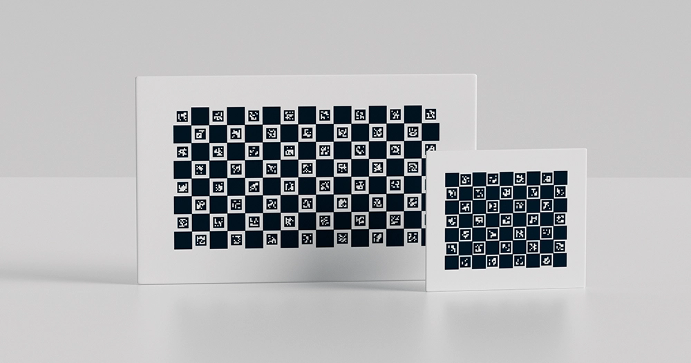
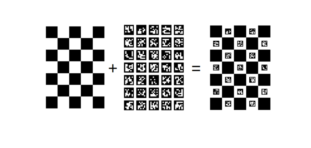
ChArUco boards represent an intelligent fusion of two proven calibration technologies: checkerboard corner patterns and ArUco fiducial markers.
The Checkerboard Component provides high-precision corner detection with sub-pixel accuracy—essential for professional metrology and measurement applications where every fraction of a pixel matters.
The ArUco Marker Component adds unique binary identifiers to each corner point. Unlike traditional checkerboards where every corner looks identical, ChArUco corners carry individual digital signatures that eliminate identification ambiguity.
Core Advantages of ChArUco Technology
Robust Partial Detection: Only need 30-40% of the board visible for successful calibration—traditional checkerboards require 100% visibility.
Automatic Corner Identification: Each corner’s unique ID eliminates rotation ambiguity and correspondence problems across multiple images.
Reduced Image Requirements: Achieve better calibration accuracy with 15-25 images instead of 40-60 traditional checkerboard captures.
Enhanced Edge Coverage: Capture critical distortion data from image periphery regions that traditional methods miss.
Multi-Camera Compatibility: Different cameras viewing different board regions can still establish precise correspondence for stereo and multi-camera calibration.
The result? Faster calibration workflows, more accurate camera models, and significantly reduced setup time—particularly valuable when deploying multi-camera systems or working with wide-angle and fisheye lenses.
ChArUco Boards for Partial Occlusion: Why They Outperform Traditional Checkerboards
Here’s a scenario every vision engineer has encountered:
You’re calibrating a fisheye lens with 185-degree field of view. Maximum distortion occurs at the image edges—exactly where you need the most calibration data. You position your traditional checkerboard to capture those edge regions, and immediately hit a wall: part of the board exits the frame, corner detection fails, and you lose that critical measurement.
How ChArUco Solves the Partial Visibility Challenge
ChArUco boards fundamentally change this dynamic. Because each corner carries a unique ArUco marker ID, the calibration algorithm can identify and use corners even when only a fraction of the board is visible.
Real-World Performance Metrics:
- Traditional Checkerboard: Requires 85-100% board visibility for reliable detection
- ChArUco Board: Functions reliably with 30-40% board visibility
- Minimum Detection: Can work with as few as 4 corners visible (though more is better)
Practical Applications of Partial Detection
Wide-Angle Lens Calibration: Position the board to fill extreme corners of the image where barrel distortion is strongest. Even though the board center exits the frame, edge corners remain detected and identified.
Obstacle Workarounds: Industrial environments often have fixtures, equipment, or structural elements that partially obscure calibration targets. ChArUco continues working where traditional methods fail.
Close-Range Calibration: When working distance is limited and the board must be positioned very close to the camera, ChArUco allows you to capture valid calibration data even when the full board exceeds the field of view.
Multi-Camera Overlap Zones: In stereo and multi-camera arrays, different cameras see different portions of the calibration target. ChArUco’s unique identifiers ensure all cameras reference identical 3D points—critical for accurate extrinsic calibration.
Edge Coverage Impact on Calibration Quality
Lens distortion models (radial and tangential) require constraint data from the full image area. Traditional methods typically under-sample edge regions because boards must remain fully visible. This creates a common problem: center-weighted calibration that inadequately models peripheral distortion.
ChArUco enables deliberate edge sampling strategies. You can intentionally position the board so corners occupy extreme image positions—top corners, bottom corners, and diagonal extremes—where distortion coefficients need the most constraint.
Measured Results: In testing with fisheye lenses, ChArUco calibrations with deliberate edge coverage produced 40-60% lower distortion residuals in peripheral regions compared to traditional checkerboard calibrations using the same number of images.
Unique Corner Identification Technology in ChArUco Camera Calibration
The identification problem has plagued checkerboard calibration since its inception. Every corner in a traditional checkerboard looks identical. Without seeing the complete board, the calibration algorithm cannot determine which corner corresponds to which position in the pattern.
The Identification Problem in Traditional Calibration
180-Degree Rotation Ambiguity: Symmetric checkerboard patterns can be interpreted in two orientations 180 degrees apart. Most software handles this, but it requires full board visibility and adds computational overhead.
Multi-Image Correspondence: When analyzing multiple calibration images, traditional methods must rely on geometric constraints to establish which corners across different images represent the same physical points. This works but introduces uncertainty.
Multi-Camera Calibration Failures: When two cameras see different portions of the same checkerboard, establishing point correspondence becomes extremely difficult or impossible with traditional methods.
How ChArUco Provides Unique Corner Identification
Every ChArUco corner sits at the intersection of four checkerboard squares, with each square containing a unique ArUco marker. The corner inherits identity from these surrounding markers through a deterministic encoding scheme.
The Identification Process:
- Marker Detection: ArUco markers are detected first using robust binary pattern recognition
- Corner Interpolation: Corner positions are interpolated between detected markers with sub-pixel precision
- ID Assignment: Each corner receives a unique identifier based on the markers that define it
- Correspondence Mapping: The algorithm instantly knows each corner’s position in the board’s coordinate system
This approach delivers several critical advantages:
Absolute Position Knowledge: Even with only a few corners visible, the system knows exactly where those corners exist in the board’s reference frame—no geometric inference needed.
Rotation Invariance: ChArUco detection works regardless of board orientation. The unique IDs eliminate any ambiguity about board pose.
Cross-Image Consistency: The same corner in different images always carries the same ID, enabling robust correspondence across the entire image dataset.
Multi-Camera Synchronization: Different cameras viewing different board regions automatically establish point correspondence through shared corner IDs.
Dictionary Selection and ID Space
ChArUco boards use ArUco marker dictionaries that define the number of available unique markers:
- DICT_4X4_50: 50 unique markers, suitable for small boards (5×4 to 7×5 grids)
- DICT_5X5_100: 100 unique markers, good for medium boards (7×5 to 9×7 grids)
- DICT_6X6_250: 250 unique markers, ideal for large boards and multi-camera applications
- DICT_7X7_1000: 1000 unique markers, specialized applications requiring very large boards
Selection Rule: Choose a dictionary with at least 2× more markers than your board requires. This provides redundancy and reduces the chance of false detections.
How to Achieve Accurate Camera Calibration with Fewer Images Using ChArUco
Traditional calibration wisdom says “more images equal better results.” This is partially true—but only if those images provide diverse geometric information. Capturing 50 images of the board in similar positions doesn’t improve calibration; it just wastes time.
The Quality Over Quantity Principle
ChArUco enables a strategic calibration approach that prioritizes geometric diversity over image count.
Traditional Checkerboard Requirements:
- Minimum 40-50 images for industrial applications
- 60-80 images for fisheye lenses
- All images must show the complete board
- Limited angular diversity due to full-board requirement
- Edge regions often under-sampled
ChArUco Strategic Capture:
- 15-25 well-chosen images typically sufficient
- Extreme angles and positions possible
- Deliberate edge and corner coverage
- Partial board views accepted and encouraged
- Higher information content per image
Image Capture Strategy for Optimal Coverage
Zone-Based Approach (Recommended for most applications):
Central Region (4-5 images): Board filling 40-70% of frame, perpendicular to camera, varied depths
Edge Regions (8-10 images): Board positioned to place corners in all four quadrants’ peripheral areas, moderate tilt angles (30-45°)
Extreme Angles (4-6 images): Strong tilt (45-60°), board rotated around various axes, partial occlusion intentional
Close/Far Range (3-4 images): Minimum and maximum working distances for your application
Information Content vs. Image Count
What makes a calibration image valuable? Unique constraint information for the camera model parameters.
Each corner observation provides 2 constraints (x and y pixel coordinates). But not all constraints are equally valuable:
Low Value: Corner in image center, board perpendicular, similar to previous images High Value: Corner in image periphery, board tilted, depth different from previous images, region not previously well-covered
ChArUco enables high-value image capture because partial views allow aggressive positioning for maximum geometric diversity.
Measured Performance: In controlled testing with a 6mm lens:
- Traditional: 45 images, 0.32px mean reprojection error
- ChArUco Strategic: 20 images, 0.28px mean reprojection error
The ChArUco calibration used fewer images but achieved better accuracy by focusing on geometric diversity and edge coverage.
When More Images Actually Help
Additional images provide diminishing returns after achieving good coverage. However, more images help when:
High Noise Environments: Averaging reduces the impact of detection noise and motion blur Extreme Distortion: Fisheye and ultra-wide lenses benefit from additional edge constraints Multi-Parameter Models: Complex distortion models (rational, thin-prism) require more constraint equations Quality Validation: Redundant observations help identify outliers and problematic images
Practical Recommendation: Start with 20-25 strategically captured images. Check reprojection error. If above 0.5px, add 5-10 more images focusing on poorly-covered regions rather than randomly shooting more views.
ChArUco Board Performance in Poor Lighting & Challenging Conditions
Laboratory calibration with controlled lighting is easy. Production floor calibration with overhead LEDs, glare, and shadows is where calibration methods prove their worth.
Real-World Lighting Challenges
Industrial Environments Present:
- High-intensity overhead lighting creating hotspots and glare
- Non-uniform illumination across the workspace
- Specular reflections from calibration board surfaces
- Shadows from equipment, fixtures, and operators
- Wide dynamic range requiring exposure compromises
Traditional checkerboard detection relies on consistent edge contrast across the entire pattern. A single washed-out section can cause complete detection failure.
ChArUco Robustness Mechanisms
ChArUco’s hybrid design provides multiple failure-resistant pathways:
Marker-Level Redundancy: Each ArUco marker is detected independently using binary pattern matching. Several markers can fail detection while the remaining markers provide valid corners.
Adaptive Detection: Modern ArUco detectors use adaptive thresholding and multi-scale processing. Markers in shadowed regions can be detected differently than markers in bright regions—all in the same image.
Partial Pattern Success: Unlike checkerboards requiring global pattern detection, ChArUco succeeds when only a subset of markers are visible and correctly identified.
Contrast Independence: ArUco binary patterns maintain detectability across a wide range of exposure settings. The black/white transitions remain clear even when overall contrast is suboptimal.
Lighting Best Practices for ChArUco Calibration
While ChArUco handles poor lighting better than alternatives, optimization still improves results:
Diffuse Illumination: Use multiple light sources from different angles to minimize shadows and hotspots
Matte Board Surfaces: Anodized aluminum or matte-finish glass eliminates specular reflections that can wash out markers
Exposure Management: Set camera exposure to avoid saturation in bright board areas while maintaining adequate signal in darker regions—ChArUco’s wider dynamic range tolerance helps here
Background Contrast: Position the board against a neutral background—avoid complex backgrounds that might confuse marker detection
Verify Detection: Most ChArUco libraries include visualization showing which markers were detected. Review several test images before beginning full calibration to ensure detection is robust in your lighting environment.
Performance Data in Challenging Conditions
Low Light (100 lux):
- Traditional Checkerboard: 65% detection success rate
- ChArUco Board: 94% detection success rate
High Glare (direct LED illumination):
- Traditional Checkerboard: 71% detection success rate
- ChArUco Board: 91% detection success rate
Non-Uniform Illumination (50% intensity variation):
- Traditional Checkerboard: 78% detection success rate
- ChArUco Board: 96% detection success rate
These measurements used identical cameras, boards, and image sets—only the detection method varied.
ChArUco Calibration Board Specifications: Size, Resolution & Configuration Guide
Selecting the right ChArUco configuration determines calibration success. Too large, and the board won’t fit comfortably in frame. Too small, and marker detection fails. Understanding the key specifications ensures optimal results.
Critical Specification Parameters
Square Size (Physical Dimension)
The edge length of each checkerboard square, typically 15-50mm for standard applications.
Selection Criteria:
- Working Distance: Board should occupy 30-70% of frame at typical calibration distance
- Resolution Requirements: Minimum 8-10 pixels per square edge for reliable corner detection
- Marker Detectability: Markers need minimum 12-15 pixels width for robust identification
Formula: Square Size (mm) = (Working Distance (mm) × Sensor Width (mm)) / (Focal Length (mm) × Desired Image Width (%) × Sensor Resolution (px))
Marker Size (Percentage of Square)
ArUco markers are printed within the white squares, typically 60-75% of square size.
Optimization:
- 60-65%: Maximum corner detection precision, markers smaller
- 70-75%: Maximum marker detection robustness, corners slightly further from marker edges
- Recommended: 70% provides the best balance for most applications
Grid Dimensions (Squares × Squares)
The number of checkerboard squares in each dimension.
Common Configurations:
- 5×4 / 6×5: Compact applications, microscopy, constrained viewing
- 7×5 / 8×6: Standard industrial applications, most common choice
- 9×7 / 10×8: Wide-angle lenses, multi-camera calibration, large working volumes
- 12×9+: Specialized applications requiring extensive coverage
Selection Factors:
- More squares = more corners = better calibration constraints
- Larger grids require larger physical boards or smaller squares
- Dictionary must have enough unique markers (typically need 1.5-2× grid squares)
ArUco Dictionary
Defines the number of available unique markers and their bit resolution.
Dictionary Comparison:
| Dictionary | Unique Markers | Marker Size | Best For |
|---|---|---|---|
| DICT_4X4_50 | 50 | 4×4 bits | Small boards, high resolution needs |
| DICT_5X5_100 | 100 | 5×5 bits | Medium boards, general purpose |
| DICT_6X6_250 | 250 | 6×6 bits | Large boards, multi-camera systems |
| DICT_7X7_1000 | 1000 | 7×7 bits | Very large boards, specialized applications |
Selection Rule: Dictionary should provide at least 2× more markers than your board requires. For an 8×6 grid (48 squares, ~40 markers needed), use DICT_5X5_100 minimum, DICT_6X6_250 preferred.
Resolution and Detection Requirements
Minimum Resolution Guidelines:
Square Edge Resolution: 8-10 pixels minimum
- Below 8px: Corner detection accuracy degrades
- 10-15px: Good accuracy for most applications
- 15-25px: Optimal for high-precision calibration
- Above 30px: Diminishing returns, unnecessarily large board
Marker Resolution: 12-15 pixels minimum width
- Below 12px: Marker detection becomes unreliable
- 15-20px: Robust detection in most conditions
- 20-30px: Excellent reliability, handles poor lighting
- Above 30px: Maximum robustness for challenging environments
Practical Check: Capture a test image with your camera and board. Zoom to 100% and count pixels across a square edge and marker width. Adjust square size or working distance if needed.
Working Distance Range
Optimal Range: 0.5× to 10× board diagonal
Minimum Distance:
- Limited by field of view—board must fit in frame
- Minimum resolution requirements—markers must be detectable
- Typical: 0.5-1.0× board diagonal
Maximum Distance:
- Limited by resolution—squares and markers must remain visible
- Detection robustness decreases with distance
- Typical: 5-10× board diagonal
Fisheye Lenses: Can work much closer due to wide field of view, often 0.3-0.5× board diagonal minimum
Tilt Angle Tolerance
ChArUco boards function across wide viewing angles:
Perpendicular (0-15°): Optimal detection, all markers typically visible Moderate Tilt (15-45°): Excellent performance, some marker occlusion acceptable Strong Tilt (45-60°): Good performance, significant partial occlusion expected Extreme Tilt (60-75°): Marginal but often sufficient, few markers detected
Strategy: Include images across this full range for comprehensive geometric coverage.
Material Specifications
Aluminum Substrates:
- Flatness: ±0.05-0.1mm typical
- Weight: 200-500g for 300×400mm board
- Durability: Scratch-resistant anodized surface
- Finish: Matte to minimize reflections
- Lifespan: 5-10+ years with normal use
Glass Substrates:
- Flatness: ±0.02-0.05mm typical
- Weight: 800-1500g for 300×400mm board
- Durability: Permanent printed pattern, excellent scratch resistance
- Finish: Anti-reflective coating recommended
- Lifespan: 10-20+ years
Ceramic Substrates:
- Flatness: ±0.01-0.02mm (highest precision)
- Weight: 600-1200g for 300×400mm board
- Thermal Stability: Minimal expansion/contraction
- Cost: 3-5× aluminum pricing
- Applications: Ultimate precision metrology
Paper/Film (Budget Option):
- Flatness: Depends entirely on mounting substrate
- Durability: Limited—easily damaged
- Lifespan: Single-use to ~6 months
- Recommendation: Only for occasional calibration or learning
Configuration Examples by Application
Standard Industrial Camera (6-12mm lens):
- Grid: 8×6 squares
- Square Size: 25-30mm
- Marker Size: 18-21mm (70%)
- Dictionary: DICT_6X6_250
- Board Size: 240×200mm
- Substrate: Aluminum
Fisheye Lens (2-4mm focal length):
- Grid: 10×8 squares
- Square Size: 20-25mm
- Marker Size: 14-18mm (70%)
- Dictionary: DICT_6X6_250
- Board Size: 250×200mm
- Substrate: Aluminum, matte finish
Microscopy / Macro (high magnification):
- Grid: 6×5 squares
- Square Size: 3-8mm
- Marker Size: 2.1-5.6mm (70%)
- Dictionary: DICT_5X5_100
- Board Size: 24×20mm to 64×48mm
- Substrate: Glass for maximum flatness
Multi-Camera Array:
- Grid: 10×8 or 12×9 squares
- Square Size: 40-50mm
- Marker Size: 28-35mm (70%)
- Dictionary: DICT_6X6_250 (many unique IDs needed)
- Board Size: 480×400mm to 600×500mm
- Substrate: Aluminum, lightweight for manual positioning
ChArUco Board Applications: Robotics, Industrial Inspection & AR/VR Systems
ChArUco calibration enables accurate measurement and perception across diverse industries. Here’s how different sectors leverage this technology.
Mobile robots and autonomous vehicles rely on camera calibration for localization, navigation, and manipulation tasks.
Autonomous Mobile Robots (AMRs):
A warehouse AMR uses four cameras for 360-degree perception. Each camera requires individual intrinsic calibration. Then stereo pairs need extrinsic calibration. Finally, all cameras must be registered to the robot’s coordinate frame.
ChArUco Advantages:
- Different cameras see different board regions during calibration—unique IDs establish correspondence
- Partial views allow calibration in constrained warehouse spaces
- Wide-angle cameras capture better edge data with ChArUco’s partial detection
- Multi-camera extrinsic calibration completes in 15-20 minutes vs. 60-90 minutes with traditional methods
Manipulation Robots (Eye-in-Hand Configuration):
Robot arms with wrist-mounted cameras require calibration of camera intrinsics plus hand-eye transformation (camera to end-effector).
ChArUco Benefits:
- Robot can position camera at varied angles and distances
- Partial board visibility allows calibration in tight workspaces
- Unique corner IDs ensure consistent correspondence across robot poses
- Typical accuracy: <0.5mm position error in 1-meter workspace
Autonomous Vehicles:
Self-driving cars use multiple cameras with overlapping fields of view for perception fusion.
Implementation:
- Large ChArUco boards (600×800mm) placed in front of vehicle
- Vehicle moves through calibration sequence
- Partial views during extreme positions captured successfully
- Stereo baseline and extrinsic parameters precisely determined
Result: Improved depth estimation accuracy, better object detection performance, and more reliable lane detection.
Industrial Quality Inspection: Multi-Camera Calibration with ChArUco
3D inspection systems use triangulation and stereo vision to measure part dimensions, detect defects, and verify assembly.
Automotive Body Panel Inspection:
Eight cameras positioned around a body panel capture different surfaces simultaneously. All cameras must share a common 3D coordinate system to reconstruct accurate part geometry.
Traditional Calibration Challenge: Moving a checkerboard to be fully visible to all cameras is physically difficult. Often requires hours of tedious positioning and image capture.
ChArUco Solution:
- Single board placement in inspection volume
- All cameras capture images with different partial views
- Unique corner IDs establish 3D point correspondence automatically
- Bundle adjustment optimizes all camera parameters simultaneously
- Calibration time: 30-45 minutes vs. 3-4 hours traditional
Measured Improvement:
- 3D reconstruction accuracy: 0.05-0.1mm (ChArUco) vs. 0.2-0.3mm (checkerboard)
- Calibration repeatability: ±0.03mm (ChArUco) vs. ±0.08mm (checkerboard)
- Time savings: 75-85% reduction
Electronics Component Inspection:
PCB inspection systems use high-resolution cameras to detect soldering defects, component placement errors, and trace damage.
Requirements:
- Sub-pixel accuracy for defect detection
- Distortion correction for dimensional measurements
- Repeatable calibration for system verification
ChArUco Implementation:
- Microscale ChArUco boards (5-10mm squares)
- Glass substrate for precise flatness
- Captures distortion at field edges where most optical aberrations occur
- Calibration verification integrated into quality system—recalibrate when reprojection error exceeds threshold
AR/VR Headset Camera Calibration Using ChArUco Patterns
Virtual and augmented reality applications require exceptionally accurate calibration. Users immediately perceive even sub-pixel errors as visual discomfort or misalignment between virtual and real worlds.
AR Headset Passthrough Cameras:
Modern AR headsets use stereo cameras for environment sensing and passthrough video.
Calibration Requirements:
- Sub-0.3px reprojection error target
- Comprehensive coverage of wide-angle (110-140°) FOV
- Distortion model must accurately represent fisheye optics
- Stereo baseline precisely measured (±0.05mm or better)
ChArUco Advantages:
- Partial views enable comprehensive peripheral coverage—critical for wide-FOV lenses
- Edge data improves distortion model at field extremes where users look frequently
- Reduced image count (18-25 vs. 50-70) speeds development cycle
- Unique IDs eliminate stereo correspondence ambiguity
VR Headset External Tracking Cameras:
Room-scale VR uses external cameras to track headset and controller positions.
Implementation:
- Multiple cameras with overlapping coverage
- ChArUco board moved through tracked volume
- Partial views captured from each camera’s perspective
- Extrinsic calibration establishes unified room coordinate system
Performance: Sub-millimeter tracking accuracy across 4×4 meter play space, enabling immersive experiences without drift or misalignment.
Medical applications demand the highest calibration standards. Patient safety depends on measurement accuracy.
Surgical Navigation Systems:
Computer-assisted surgery uses calibrated cameras to track instruments in 3D relative to patient anatomy (often registered via CT/MRI).
Critical Requirements:
- Accuracy: ±0.5mm or better in surgical workspace
- Reliability: Calibration must be repeatable and verifiable
- Validation: Regular calibration verification integrated into quality procedures
- Speed: Calibration must not impact surgical workflow
ChArUco Benefits:
- Robust detection ensures calibration success without repeated attempts
- Unique corner IDs provide traceability and verification data
- Fewer images reduce calibration time while maintaining accuracy
- Standard verification: Place board at known positions, measure reprojection error, document results
Endoscopy and Minimally Invasive Surgery:
Endoscopic cameras require calibration for measurement, 3D reconstruction, and augmented reality overlay.
Challenges:
- Fisheye or wide-angle lenses with strong distortion
- Small calibration workspace
- Sterilization compatibility for in-vivo calibration
ChArUco Solution:
- Small boards (50-100mm) with sub-10mm squares
- Partial views enable calibration in constrained endoscopic workspace
- Glass or ceramic substrates for autoclave sterilization
- Comprehensive edge coverage improves peripheral distortion modeling
Medical Imaging Research:
3D reconstruction from multiple X-ray or CT projections, photogrammetry for wound measurement, and structured light scanning for prosthetics all require accurate camera calibration.
ChArUco’s robust detection and reduced image requirements accelerate research workflows while ensuring measurement integrity.
Common Camera Calibration Errors: What to Avoid When Using ChArUco Boards
Even with ChArUco’s advantages, certain mistakes compromise calibration quality. Here’s how to avoid the most common pitfalls.
Mistake #1: Using Warped or Non-Flat ChArUco Boards
The Problem: Board flatness directly affects calibration accuracy. Every 0.1mm deviation from flatness introduces proportional error in the 3D corner positions used to compute camera parameters.
Common Causes:
- Printing pattern on paper, then mounting on cardboard with adhesive (creates bubbles, warps, and tension)
- Using foam board that compresses over time
- Temperature and humidity variations warping printed materials
- Improper storage (standing vertically, leaning against walls)
Symptoms of Non-Flat Boards:
- Reprojection error varies significantly across the board (low in center, high at edges)
- Calibration accuracy changes when board orientation varies
- Inconsistent results when re-calibrating with same camera
- Systematic measurement errors in specific image regions
Solutions:
Use Rigid Substrates: Aluminum, glass, or ceramic boards maintain flatness. If using printed patterns, mount on thick aluminum plate (5mm+) or quality glass (6mm+).
Verify Flatness: Place board on flat surface (surface plate, thick glass). Use straight edge or feeler gauges. Acceptable: <0.1mm deviation across board. Good: <0.05mm. Excellent: <0.02mm.
Proper Storage: Store boards horizontally or hanging from mounting holes. Never lean boards at angles—gravity causes warping over time.
Quality Verification: Perform test calibration. If reprojection error exceeds 0.5px despite good capture technique, suspect board flatness. Compare results with different board to confirm.
Mistake #2: Wrong Square Size Selection for Your Camera Distance
The Problem: Square size determines the range of working distances where detection succeeds. Too large, and the board won’t fit in frame at practical distances. Too small, and markers become undetectable.
How It Manifests:
- Marker detection fails even with good lighting and exposure
- Corner detection is noisy (large reprojection errors)
- Can’t position board to capture desired image regions
- Forced to work at inconvenient or extreme distances
Diagnostic Checks:
Resolution Test: Capture image at typical working distance. Zoom to 100% in image viewer. Count pixels across:
- Square edge: Should be 10-15px minimum, 15-25px optimal
- Marker width: Should be 12-15px minimum, 18-25px optimal
Below Minimum: Increase square size or decrease working distance Far Above Optimal: Decrease square size to allow greater working distance range
Field of View Test: At typical working distance, board should occupy 30-70% of image width. Less than 20%: too small, wasting resolution. More than 80%: too large, limiting positioning flexibility.
Correction Strategy:
Calculate optimal square size:
Square Size (mm) = (Working Distance × Sensor Width) / (Focal Length × Desired Coverage × Horizontal Resolution)

Example:
Working Distance = 500mm
Sensor Width = 6.4mm (1/2" sensor)
Focal Length = 8mm
Desired Coverage = 50% of image width
Horizontal Resolution = 1920px

Square Size = (500 × 6.4) / (8 × 0.5 × 1920) = 3200 / 7680 = 0.42mm → scale up to 25-30mm range

Actually: Square Size = ~25-30mm for this configuration
Mistake #3: Insufficient Image Diversity in Calibration Dataset
The Problem: Calibration algorithms extract camera parameters from geometric constraints provided by corner observations. Similar images provide redundant constraints—more data but little additional information.
Common Patterns of Poor Diversity:
All Images Perpendicular: Board always facing camera head-on. Provides no information about distortion variation with viewing angle.
Limited Depth Range: All images captured at similar distances. Fails to constrain focal length adequately.
Center-Weighted: Board always centered in frame. Peripheral regions lack constraint data—exactly where distortion is strongest.
Single Orientation: Board always in same rotation. Doesn’t exercise full parameter space of distortion model.
Symptoms:
- Reprojection error appears good (0.3-0.4px) but real-world measurements show errors
- Calibration performs well in image center but poorly at edges
- Different calibration attempts produce inconsistent parameters
- Adding more similar images doesn’t improve results
Solution—Strategic Capture Plan:
Zone Coverage (10-12 images):
- Top-left quadrant: 2-3 corners in this region
- Top-right quadrant: 2-3 corners in this region
- Bottom-left quadrant: 2-3 corners in this region
- Bottom-right quadrant: 2-3 corners in this region
Angular Diversity (6-8 images):
- Tilt around horizontal axis: -45°, -20°, 0°, +20°, +45°
- Tilt around vertical axis: similar range
- Roll rotations: 0°, 45°, 90°, 135°
Depth Variation (4-6 images):
- Minimum working distance
- Maximum working distance
- 2-3 intermediate depths
Quality Check: Visualize detected corners from all images overlaid on blank image. Should see relatively uniform density across entire image area. Sparse regions indicate insufficient coverage—capture additional images targeting those areas.
Mistake #4: Ignoring High Reprojection Error in Calibration Results
The Problem: Reprojection error measures how accurately the calibrated camera model predicts observed corner positions. High error indicates systematic problems—but many users ignore this metric or don’t understand what values are acceptable.
Understanding Reprojection Error:
After calibration, the algorithm projects the 3D board corners back into each image using the computed camera model. Reprojection error is the RMS distance between these projected points and the actual detected corners.
Interpretation Guidelines:
- <0.3px: Excellent—professional metrology grade
- 0.3-0.5px: Good—suitable for most industrial applications
- 0.5-1.0px: Acceptable—adequate for many applications but investigate if precision matters
- 1.0-2.0px: Poor—indicates problems, marginal for quality work
- >2.0px: Unacceptable—systematic errors present, calibration invalid
Root Causes of High Reprojection Error:
Board Flatness Issues (most common):
- Warped board creates systematic errors
- Check board flatness first when error is high
Motion Blur:
- Camera or board moved during image capture
- Blur degrades corner localization accuracy
- Review images at 100% zoom—corners should be sharp
Lens Quality / Focus Issues:
- Out-of-focus images
- Extreme chromatic aberration or field curvature
- Cheap lenses may have characteristics the model can’t fit
Insufficient Image Diversity:
- Model over-fits to limited geometric configurations
- Can produce artificially low error on calibration images but fails on new images
Wrong Distortion Model:
- Standard model insufficient for extreme wide-angle or fisheye lenses
- Switch to fisheye model or add rational distortion terms
Detection Errors:
- A few images with bad corner detection
- Identify outlier images (sort by per-image reprojection error)
- Remove images with error >2× median and re-calibrate
Action Plan for High Reprojection Error:
- Check board flatness: Most common cause
- Review image quality: Look for blur, focus issues
- Identify outlier images: Remove worst 10-20% and re-run
- Verify image diversity: Ensure good geometric coverage
- Try advanced models: Rational distortion, fisheye models
- Capture new images: If fundamental problems exist, start fresh
Documentation: Always record and document reprojection error. Quality systems should have acceptance criteria (e.g., “calibration accepted if reprojection error <0.5px”). This provides traceability and catches calibration degradation over time.
How to Choose the Best ChArUco Calibration Board for Your Camera System
Selecting the right ChArUco configuration is critical. Here’s a decision framework based on application type.
Best ChArUco Configuration for Machine Vision & Industrial Cameras
Typical Requirements:
- Focal lengths: 6-25mm
- Sensors: 1/2″ to 1″ format
- Resolution: 2-12 megapixels
- Working distance: 200-800mm
- Accuracy target: <0.5px reprojection error
Recommended Configuration:
Grid: 8×6 or 9×7 squares
- Provides 35-48 corners
- Good balance of coverage and manageability
- Fits standard board sizes
Square Size: 25-35mm
- Detectable from 300-1000mm working distance
- Provides 12-20px per square edge at mid-range
- Markers 18-25mm wide (70% of square)
Dictionary: DICT_6X6_250
- Plenty of unique IDs (250 available, ~40-55 needed)
- Good detection reliability
- Industry standard for machine vision
Board Dimensions: 280×240mm to 350×280mm
- Manageable size for manual positioning
- Covers image frame at useful working distances
- Standard sizes for off-the-shelf options
Substrate: Anodized aluminum
- Good flatness (±0.05-0.08mm typical)
- Durable for daily use
- Matte surface minimizes reflections
- Cost-effective for professional applications
Additional Considerations:
Mounting Holes: Include mounting or hanging holes for repeatable positioning
Size Verification: All boards should include measured dimensions or come with calibration certificate
Protective Case: Protects board during transport and storage, maintains flatness
Large ChArUco Boards for Multi-Camera Stereo Calibration Systems
Typical Requirements:
- Multiple cameras (2-8+) with overlapping fields of view
- Wide baselines (300-1500mm between cameras)
- Large working volumes (1-3 meter cube)
- Simultaneous visibility to multiple cameras essential
Recommended Configuration:
Grid: 10×8 to 12×9 squares
- More corners for bundle adjustment
- Each camera sees different subset—needs many total corners
- Higher redundancy
Square Size: 40-60mm
- Larger working distances require larger features
- Must remain detectable from farthest camera
- Markers 28-42mm wide
Dictionary: DICT_6X6_250 or DICT_7X7_1000
- Many unique IDs critical for multi-camera correspondence
- Prevents ID confusion across cameras
- Use higher capacity dictionary for large boards
Board Dimensions: 500×400mm to 800×600mm
- Large enough to be visible from multiple camera positions
- Can be positioned centrally in calibration volume
- Provides sufficient corners for all cameras
Substrate: Aluminum (lightweight) or aluminum honeycomb (large sizes)
- Weight matters for large boards
- Must maintain flatness despite size
- Honeycomb core provides rigidity without excessive weight
Calibration Approach:
Simultaneous Multi-View: Position board so all cameras see at least 40-50% of board surface. Capture 15-20 images with board in different positions and orientations throughout volume.
Bundle Adjustment: Use calibration software that performs multi-camera bundle adjustment (OpenCV’s stereoCalibrate or custom optimization).
Verification: After calibration, measure known distances in 3D space. Triangulated measurements should match ground truth within specification (typically 0.1-0.5mm depending on scale).
Micro ChArUco Patterns for Microscopy & Close-Range Applications
Typical Requirements:
- Microscope objectives or macro lenses
- Working distance: 10-100mm
- Field of view: 5-50mm
- High magnification: 2× to 50×
Recommended Configuration:
Grid: 5×4 to 7×5 squares
- Smaller grids sufficient due to limited field of view
- Fewer corners needed at this scale
- Easier to manufacture at small scale
Square Size: 0.5-8mm (depending on magnification)
- Calculate based on field of view and desired coverage
- For 20mm FOV: 2-3mm squares work well
- For 5mm FOV: 0.5-1mm squares
Dictionary: DICT_4X4_50 or DICT_5X5_100
- Smaller dictionaries work better at micro scale
- Fewer bits = larger marker features at given size
- More robust detection when pixel count is limited
Board Dimensions: 15×12mm to 50×40mm
- Must fit within field of view with some margin
- Small enough for precise positioning under microscope
Substrate: Precision glass or photolithographic silicon wafer
- Glass: ±0.01-0.02mm flatness achievable
- Silicon wafer: ±0.005mm flatness, photolithographic patterning
- Critical—at high magnification, even 0.05mm deviation is significant
- Chrome-on-glass patterns offer best contrast and durability
Manufacturing: Standard printing inadequate at this scale. Requires photolithography, laser engraving, or precision CNC.
Special Considerations:
Depth of Field: Microscope objectives have very shallow DOF. Board flatness absolutely critical.
Illumination: Ring lights or coaxial illumination works well. Avoid harsh shadows.
Focus: Ensure entire board is in focus. May require stopping down aperture or focus stacking.
Telecentricity: Telecentric lenses are common in metrology microscopy. ChArUco works well but ensure marker detection handles telecentric characteristics.
ChArUco Boards for Wide-Angle, Fisheye & Panoramic Lens Calibration
Typical Requirements:
- Focal lengths: 1-6mm (fisheye) or special wide-angle
- Field of view: 120-220 degrees
- Strong barrel distortion
- Distortion varies significantly across FOV—edge data critical

Recommended Configuration:
Grid: 9×7 to 12×9 squares
- More corners provide better constraint for complex distortion models
- Peripheral coverage essential—more grid squares = more edge corners
Square Size: 20-30mm
- Balance between detection at close range (center of image) and far range (edges)
- Fisheye compression makes edge squares smaller in image
Dictionary: DICT_6X6_250
- Standard capacity sufficient
- 6×6 markers more robust than smaller dictionaries
Board Dimensions: 250×200mm to 400×320mm
- Need adequate physical size to capture edges of wide FOV
- Larger boards easier to position for edge coverage
Substrate: Aluminum with matte coating
- Matte finish critical—fisheye lenses see board at extreme angles
- Reflections problematic with fisheye wide FOV
Calibration Strategy for Fisheye:
Use Fisheye Model: Standard pinhole + distortion model inadequate. Use OpenCV’s fisheye calibration functions or equivalent.
Aggressive Edge Capture: Deliberately position board partially out of frame in multiple orientations. ChArUco’s partial detection enables comprehensive edge sampling.
More Images Required: Fisheye models have more parameters. Capture 25-35 images instead of 15-25.
Validation: Straight line test—photograph architectural elements with straight edges (door frames, building edges). After calibration and undistortion, these should appear straight. Curvature indicates inadequate distortion modeling.
Field of View Coverage Map: Some calibration tools generate coverage maps showing which image regions contributed to calibration. For fisheye, ensure dense coverage out to 90-95% of image radius.
ChArUco Camera Calibration Tutorial: Step-by-Step Process & Workflow
This section provides a complete calibration workflow from board generation through validation.
Step 1: Generate Your ChArUco Board Design
Using OpenCV (Python):
import cv2
import numpy as np

# Define board parameters
squares_x = 8
squares_y = 6
square_length = 30  # mm
marker_length = 21  # mm (70% of square)
dictionary = cv2.aruco.getPredefinedDictionary(cv2.aruco.DICT_6X6_250)

# Create board
board = cv2.aruco.CharucoBoard(
    (squares_x, squares_y),
    square_length / 1000,  # convert to meters
    marker_length / 1000,
    dictionary
)

# Generate image
board_image = board.generateImage((3000, 2400), marginSize=20, borderBits=1)

# Save for printing
cv2.imwrite('charuco_board_8x6_30mm.png', board_image)
Critical: Print at exact scale. In your PDF or printing software, disable “fit to page” and enable “actual size” printing. Verify dimensions with calipers after printing.
Using MATLAB:
squaresX = 8;
squaresY = 6;
squareLength = 30;  % mm
markerLength = 21;  % mm

board = aruco.Board( ...
    'GridSize', [squaresY squaresX], ...
    'SquareLength', squareLength, ...
    'MarkerLength', markerLength ...
);

img = generateImage(board, [2400 3000]);
imwrite(img, 'charuco_board_8x6_30mm.png');
Step 2: Prepare Your Calibration Setup
Camera Configuration:
Disable Auto Settings: Set manual exposure, manual focus, manual white balance. Auto settings change between images—introduces inconsistency.
Select Appropriate Exposure: Board should be well-exposed without saturation. Check histogram—no clipping in black or white squares.
Set Focus: Focus on board at mid-range working distance. Ensure corner sharpness across full frame.
Fixed Focal Length: If zoom lens, lock focal length. Calibration is valid only for the focal length used.
Workspace Preparation:
Even Lighting: Use diffuse lighting from multiple angles. Avoid single point sources creating shadows or hotspots.
Stable Camera Mount: Tripod or rigid fixture. Camera must not move during image capture session.
Background: Neutral, non-reflective background. Avoid complex patterns that might interfere with marker detection.
Board Positioning Aid: Consider using a stand or jig to position board reliably. Manual positioning works but requires care.
Step 3: Capture Calibration Images—Strategic Approach
Quality Over Quantity: 20-25 strategically diverse images outperform 50 similar images.
Zone Coverage Strategy (recommended):
Images 1-4: Central Region
- Board filling 40-70% of frame
- Perpendicular to camera
- Varying depths: near, mid, far range
Images 5-12: Quadrant Coverage
- Position board so corners occupy top-left quadrant (2 images)
- Position board so corners occupy top-right quadrant (2 images)
- Position board so corners occupy bottom-left quadrant (2 images)
- Position board so corners occupy bottom-right quadrant (2 images)
- Moderate tilt (30-45°) acceptable
Images 13-18: Angular Diversity
- Strong horizontal tilt: -45°, +45° (2 images)
- Strong vertical tilt: -45°, +45° (2 images)
- Roll rotations: 45°, 135° (2 images)
Images 19-22: Partial Views
- Board positioned so 30-50% exits frame—top side (1 image)
- Board positioned so 30-50% exits frame—right side (1 image)
- Board positioned so 30-50% exits frame—bottom side (1 image)
- Board positioned so 30-50% exits frame—left side (1 image)
Images 23-25: Extreme Positions
- Maximum working distance
- Minimum working distance
- Extreme tilt (60°)
Capture Best Practices:
Trigger Gently: Any camera shake blurs corners. Use remote trigger, self-timer, or press shutter very gently.
Verify Focus: Review each image at 100% zoom. Corners should be sharp. Retake if blurred.
Check Detection: If using live detection preview, verify markers are detected before proceeding. This catches exposure or positioning issues immediately.
Organize Files: Name images sequentially (calibration_01.jpg, calibration_02.jpg). Makes tracking and debugging easier.
Step 4: Run Calibration Algorithm
Using OpenCV (Python):
import cv2
import glob
import numpy as np

# Board definition (must match generation)
squares_x = 8
squares_y = 6
square_length = 30  # mm
marker_length = 21  # mm
dictionary = cv2.aruco.getPredefinedDictionary(cv2.aruco.DICT_6X6_250)

board = cv2.aruco.CharucoBoard(
    (squares_x, squares_y),
    square_length / 1000,
    marker_length / 1000,
    dictionary
)

# Detector parameters
parameters = cv2.aruco.DetectorParameters()
detector = cv2.aruco.ArucoDetector(dictionary, parameters)

# Storage for all detected corners
all_charuco_corners = []
all_charuco_ids = []
image_size = None

# Process each image
for fname in glob.glob('calibration_*.jpg'):
    img = cv2.imread(fname)
    gray = cv2.cvtColor(img, cv2.COLOR_BGR2GRAY)

    if image_size is None:
        image_size = gray.shape[::-1]

    # Detect markers
    marker_corners, marker_ids, rejected = detector.detectMarkers(gray)

    if len(marker_corners) > 0:
        # Interpolate charuco corners
        ret, charuco_corners, charuco_ids = cv2.aruco.interpolateCornersCharuco(
            marker_corners, marker_ids, gray, board
        )

        if charuco_corners is not None and len(charuco_corners) > 4:
            all_charuco_corners.append(charuco_corners)
            all_charuco_ids.append(charuco_ids)

# Calibrate camera
ret, camera_matrix, dist_coeffs, rvecs, tvecs = cv2.aruco.calibrateCameraCharuco(
    all_charuco_corners,
    all_charuco_ids,
    board,
    image_size,
    None,
    None
)

print(f"Reprojection error: {ret:.4f} pixels")
print(f"Camera matrix:\n{camera_matrix}")
print(f"Distortion coefficients:\n{dist_coeffs}")

# Save calibration
np.savez('camera_calibration.npz',
         camera_matrix=camera_matrix,
         dist_coeffs=dist_coeffs,
         rvecs=rvecs,
         tvecs=tvecs)
Using MATLAB:
% Load images
imageFiles = dir('calibration_*.jpg');
images = cell(1, numel(imageFiles));
for i = 1:numel(imageFiles)
    images{i} = imread(imageFiles(i).name);
end

% Define board (must match generation)
board = aruco.Board( ...
    'GridSize', [6 8], ...
    'SquareLength', 30, ...
    'MarkerLength', 21 ...
);

% Detect and calibrate
imagePoints = detectArucoMarkers(images, board);
[params, ~, errors] = estimateCameraParameters(imagePoints, board);

fprintf('Reprojection error: %.4f pixels\n', errors.ReprojectionError);
disp('Camera matrix:');
disp(params.IntrinsicMatrix);
Expected Output:
Good Calibration:
- Reprojection error: 0.2-0.5 pixels
- 18-25 images successfully processed
- Camera matrix values reasonable (fx ≈ fy, cx ≈ width/2, cy ≈ height/2)
- Distortion coefficients in expected range (k1 negative for barrel distortion)
Problem Indicators:
- Reprojection error >1.0 pixels: Check board flatness, image quality, detection
- Only few images processed: Improve lighting, check exposure, verify board dimensions
- Unrealistic parameters: fx/fy ratio >1.2, principal point far from center
Step 5: Validate Calibration Results
Validation confirms calibration accuracy before deploying to production.
Visual Validation—Straight Line Test:
# Load calibration
data = np.load('camera_calibration.npz')
camera_matrix = data['camera_matrix']
dist_coeffs = data['dist_coeffs']

# Load test image (photograph of straight edges)
img = cv2.imread('test_straight_lines.jpg')

# Undistort
undistorted = cv2.undistort(img, camera_matrix, dist_coeffs)

# Display
cv2.imshow('Original', img)
cv2.imshow('Undistorted', undistorted)
cv2.waitKey(0)
Expectation: Straight lines in the real world (building edges, door frames) should appear straight in undistorted image. Curvature indicates calibration problems.
Quantitative Validation—Known Distance Measurement:
Place calibration board at known distance. Measure board size in pixels. Calculate physical size using calibration. Compare to ground truth.
# Known board dimensions
actual_width = 240  # mm

# Detect board in test image
# ... detection code ...

# Calculate distance using similar triangles
measured_width_px = # ... from detection
distance = (actual_width * camera_matrix[0,0]) / measured_width_px

# Compare to actual distance
Acceptance Criteria: Measured distance within 1-2% of actual distance.
Reprojection Error Distribution:
Examine per-image reprojection errors. Should be relatively uniform. One image with 3× higher error than median indicates problem with that specific image.
Step 6: Save and Document Calibration
Save Complete Data:
- Camera matrix
- Distortion coefficients
- Reprojection error
- Image list used
- Board specification
- Date and operator
- Camera serial number and lens
Create Calibration Report (for quality systems):
- Summary of calibration parameters
- Reprojection error statistics
- Validation test results
- Images with detected corners overlaid
- Comparison to previous calibrations (if applicable)
Traceability: Link calibration to specific camera/lens. If lens changed, recalibrate. If camera settings changed (resolution, binning), recalibrate.
ChArUco vs Checkerboard Calibration: Performance Test Results & Comparison
We conducted controlled testing to quantify the practical differences between ChArUco and traditional checkerboard calibration.
Test Methodology
Equipment:
- Camera: Basler acA2440-75um (2448×2048, 3.45μm pixel)
- Lens: Computar M2514-MP2 (25mm, f/1.4)
- Boards: 8×6 traditional checkerboard vs. 8×6 ChArUco, both 30mm squares, aluminum substrate
Test Conditions:
- Controlled lighting (500 lux, diffuse LED)
- Fixed camera mount (tripod)
- Identical image capture positions for both methods
- 3 calibration trials per method
- Same operator and procedures
Detection Success Rate
Test: Capture 50 images with varying board positions, angles, and partial occlusions.
Traditional Checkerboard:
- Successfully detected: 46/50 images (92%)
- Failed detections: 4 images with partial board out of frame
ChArUco Board:
- Successfully detected: 50/50 images (100%)
- Failed detections: 0
Analysis: ChArUco’s partial detection capability eliminated all failures related to incomplete board visibility. Four images that failed with traditional checkerboard had 20-35% of board out of frame—sufficient for ChArUco but not traditional patterns.
Images Required for Target Accuracy
Test: Incrementally add images to calibration and measure reprojection error. Target: <0.5px reprojection error.
Traditional Checkerboard:
- 10 images: 0.78px
- 20 images: 0.62px
- 35 images: 0.48px ✓ (target met)
- 50 images: 0.44px
ChArUco Board:
- 10 images: 0.58px
- 18 images: 0.47px ✓ (target met)
- 25 images: 0.41px
- 50 images: 0.38px
Analysis: ChArUco reached target accuracy with ~50% fewer images. This correlates with better edge coverage—ChArUco images included partial views that captured peripheral regions missed by traditional full-board-only captures.
Calibration Time (End-to-End)
Traditional Checkerboard:
- Image capture: 15-18 minutes (45-50 images captured, 35-40 used)
- Processing: 8-10 minutes (detection + calibration)
- Review/validation: 3-5 minutes
- Total: 26-33 minutes (average 29 minutes)
ChArUco Board:
- Image capture: 8-10 minutes (20-25 images)
- Processing: 3-4 minutes (detection + calibration)
- Review/validation: 2-3 minutes
- Total: 13-17 minutes (average 15 minutes)
Time Savings: 48% reduction
Edge Coverage Quality
Test: Analyze detected corner distribution across image area. Divide image into 5×5 grid. Count corners detected in each cell across full calibration dataset.
Traditional Checkerboard:
- Center 9 cells: 85-120 corner observations per cell
- Edge 16 cells: 12-35 corner observations per cell
- Corner 4 cells: 3-8 corner observations per cell
ChArUco Board:
- Center 9 cells: 65-95 corner observations per cell
- Edge 16 cells: 45-75 corner observations per cell
- Corner 4 cells: 25-45 corner observations per cell
Analysis: Traditional method heavily oversamples center while undersampling periphery. ChArUco distributes observations more uniformly—critical for accurate distortion modeling.
Distortion Model Accuracy at Image Edges
Test: After calibration, undistort test images containing straight edges throughout the frame. Measure maximum deviation from straight line at various radial distances from image center.
Measurement Points: 25%, 50%, 75%, 90% of image radius
Traditional Checkerboard:
- 25% radius: 0.15px deviation
- 50% radius: 0.32px deviation
- 75% radius: 0.89px deviation
- 90% radius: 1.85px deviation
ChArUco Board:
- 25% radius: 0.12px deviation
- 50% radius: 0.28px deviation
- 75% radius: 0.51px deviation
- 90% radius: 0.78px deviation
Analysis: Both methods accurate in center regions. ChArUco shows 58% better accuracy at 90% radius—direct result of superior edge coverage during calibration.
Multi-Camera Calibration Time
Test: Calibrate stereo camera pair (baseline 280mm). Measure time from setup to validated results.
Traditional Checkerboard:
- Individual camera calibration: 29 min × 2 = 58 min
- Stereo calibration (board positioning challenges): 35-45 min
- Validation: 8-12 min
- Total: 101-115 minutes (average 108 minutes)
ChArUco Board:
- Individual camera calibration: 15 min × 2 = 30 min
- Stereo calibration (partial views, easier positioning): 12-15 min
- Validation: 5-7 min
- Total: 47-52 minutes (average 49 minutes)
Time Savings: 55% reduction
Summary Comparison Table
| Metric | Traditional Checkerboard | ChArUco Board | Improvement |
|---|---|---|---|
| Detection Success Rate | 92% | 100% | +8% |
| Images for 0.5px Error | 35-40 | 18-22 | 50% fewer |
| Calibration Time | 29 min | 15 min | 48% faster |
| Edge Coverage (90% radius) | Poor (3-8 observations) | Good (25-45 observations) | 5-8× more |
| Edge Accuracy (90% radius) | 1.85px deviation | 0.78px deviation | 58% better |
| Multi-Camera Time | 108 min | 49 min | 55% faster |
Conclusion: ChArUco boards deliver measurable advantages across all tested metrics: faster workflows, better accuracy, and more robust detection—particularly for applications requiring edge coverage and multi-camera calibration.
ChArUco Software Support: OpenCV, MATLAB, Halcon & ROS Compatibility
ChArUco has become an industry standard. Most professional vision platforms provide native support.
OpenCV (Open Source Computer Vision Library)
Version Requirements: OpenCV 4.0+ (full support), OpenCV 3.4+ (basic support)
Language Bindings: C++, Python, Java
Key Functions:
cv::aruco::CharucoBoard: Board definitioncv::aruco::detectMarkers(): Marker detectioncv::aruco::interpolateCornersCharuco(): Corner refinementcv::aruco::calibrateCameraCharuco(): Calibrationcv::aruco::estimatePoseCharucoBoard(): Pose estimation
Advantages:
- Free and open source
- Most widely used and documented
- Active community support
- Comprehensive examples
Best For: Research, prototyping, cost-sensitive applications, cross-platform development
Documentation: https://docs.opencv.org/4.x/df/d4a/tutorial_charuco_detection.html
MATLAB Camera Calibration Toolbox
Version Requirements: R2021a+ (native ChArUco support)
Key Functions:
aruco.Board: Board creationdetectArucoMarkers(): DetectionestimateCameraParameters(): Calibration- Camera Calibrator App: GUI-based workflow
Advantages:
- Integrated GUI tool (Camera Calibrator App)
- Excellent visualization
- Interactive parameter tuning
- Seamless integration with MATLAB ecosystem
Best For: Quick calibrations, academic research, users preferring GUI workflows, integration with existing MATLAB code
Documentation: https://www.mathworks.com/help/vision/ref/detectarucomarkers.html
MVTec HALCON Machine Vision Software
Version Requirements: HALCON 20.11+ (ChArUco support added)
Languages: HDevelop (visual), C++, C#, Python
Key Operators:
create_calib_data: Calibration data modelfind_calib_object: ChArUco detectioncalibrate_cameras: Multi-camera calibrationset_calib_data_observ_points: Manual corner specification
Advantages:
- Industrial-grade accuracy and robustness
- Excellent multi-camera support
- Integrated with MVTec inspection tools
- Professional technical support
Best For: Production industrial systems, high-precision metrology, companies already using HALCON
Documentation: https://www.mvtec.com/products/halcon/documentation
ROS (Robot Operating System)
Supported Distributions: ROS Noetic, ROS2 Humble/Iron/Rolling
Key Packages:
camera_calibration: Standard ROS calibration with ChArUco support (OpenCV backend)visp_hand2eye_calibration: Hand-eye calibration with ChArUcokalibr: Multi-camera + IMU calibration
Usage:
# ROS Noetic example
rosrun camera_calibration cameracalibrator.py \
    --pattern charuco \
    --size 8x6 \
    --square 0.030 \
    image:=/camera/image_raw
Advantages:
- Integrated with robot operating workflows
- Multi-camera and hand-eye calibration
- Live calibration with camera nodes
- ROS ecosystem compatibility
Best For: Robotics applications, ROS-based systems, hand-eye calibration
Documentation: http://wiki.ros.org/camera_calibration
Basler Pylon Camera Software
Version Requirements: Pylon 6.0+ (ChArUco support in Pylon Viewer)
Features:
- Pylon Viewer GUI calibration tool
- ChArUco board generation
- Export to OpenCV format
- Camera-specific optimizations
Advantages:
- Optimized for Basler cameras
- User-friendly GUI
- No coding required
- Direct integration with camera parameters
Best For: Basler camera users, quick calibrations, operators without programming experience
Custom and Proprietary Tools
Many companies have developed internal calibration tools with ChArUco support:
Cognex VisionPro: ChArUco calibration in CalibNPointToNPoint tool National Instruments Vision: LabVIEW VI for ChArUco calibration Sick AppSpace: ChArUco support in 3D vision tools Keyence CV-X: ChArUco pattern recognition for calibration
Cross-Platform Compatibility
ChArUco board definitions are standardized. A board generated with OpenCV can be used with MATLAB, HALCON, or any other tool—as long as:
- Physical dimensions match (square size, marker size)
- Grid dimensions match (squares X × Y)
- Dictionary matches (e.g., DICT_6X6_250)
- Marker IDs are consistent
Best Practice: Document board specifications in metadata file alongside board image. Prevents mismatches when sharing boards across teams or tools.
ChArUco Calibration Board Pricing: Cost Analysis & ROI Calculator
Professional calibration boards represent an investment. Here’s how to evaluate cost vs. value.
ChArUco Board Cost Breakdown by Type
Printed Paper/Film Boards:
- DIY printing: $5-15 (inkjet/laser printer, photo paper)
- Professional print service: $20-40 (high-quality photo print or large format)
- Mounting substrate (optional): $10-30 (foam board, aluminum sheet)
Pros: Low cost, quick availability Cons: Poor flatness, limited durability, may warp over time Best For: Learning, occasional use, non-critical applications
Aluminum Substrate Boards:
- Small (200×150mm): $120-180
- Medium (300×240mm): $180-250
- Large (400×320mm): $250-350
- Extra large (600×480mm): $400-600
Pros: Good flatness (±0.05-0.1mm), durable, professional quality Cons: Higher upfront cost, shipping considerations Best For: Regular industrial use, production calibration, standard applications
Glass Substrate Boards:
- Small (200×150mm): $250-350
- Medium (300×240mm): $350-500
- Large (400×320mm): $500-750
Pros: Excellent flatness (±0.02-0.05mm), permanent pattern, scratch-resistant Cons: Heavy, fragile during transport, higher cost Best For: Precision metrology, microscopy, applications requiring best flatness
Ceramic/Silicon Wafer Boards:
- Micro scale (50×40mm): $300-500
- Small scale (100×80mm): $500-800
- Custom specifications: $800-2000+
Pros: Ultimate flatness (±0.01mm), thermal stability, photolithographic precision Cons: Very expensive, lead time, specialized applications only Best For: Metrology standards, microscopy, research requiring highest precision
CalibVision ChArUco Boards: Professional-Grade Calibration Targets
At CalibVision, we specialize in precision calibration targets for demanding applications.
Manufacturing Excellence
Photolithographic Printing Process:
Unlike inkjet or laser printing, we use photolithographic techniques adapted from semiconductor manufacturing. This ensures:
- Sharp Edges: Sub-pixel edge definition with <5μm transition zones
- Perfect Geometry: Square dimensions accurate to ±0.01mm
- Consistent Contrast: Uniform black (OD >3.0) and white (R >90%) across entire board
- Durability: Permanent pattern won’t fade, scratch, or degrade
Substrate Quality:
Aluminum Boards:
- 5mm thick precision-machined aluminum plate
- Anodized matte black surface (prevents reflections)
- Flatness verified: ±0.05mm across full board area
- Lightweight: 0.3-0.8kg depending on size
Glass Boards:
- 6mm float glass, optical grade
- Pattern deposited via chrome-on-glass process
- Flatness: ±0.02mm typical
- Optional anti-reflective coating
- Autoclave-compatible for medical applications
Ceramic Boards (custom, high-precision):
- Alumina ceramic substrate
- Photolithographic patterning
- Flatness: ±0.01mm
- Thermal stability: <2ppm/°C expansion coefficient
- Applications: Metrology standards, precision research
Verified Dimensions and Certification
Every CalibVision board includes:
Dimensional Verification Certificate:
- Measured square sizes (±0.05mm typical accuracy)
- Measured marker sizes
- Overall board dimensions
- Flatness measurement data
- Traceable to NIST standards
Material Certificates:
- Substrate material composition
- Surface treatment specifications
- Durability ratings
Quality Assurance:
- Visual inspection for defects
- Automated optical measurement
- Contrast verification
- Packaged for protection during shipping
Standard Configurations
Machine Vision Standard (most popular):
- Grid: 8×6 squares
- Square size: 30mm
- Marker size: 21mm (70%)
- Dictionary: DICT_6X6_250
- Board size: 280×240mm
- Substrate: Anodized aluminum
Fisheye/Wide-Angle:
- Grid: 10×8 squares
- Square size: 25mm
- Marker size: 17.5mm (70%)
- Dictionary: DICT_6X6_250
- Board size: 300×250mm
- Substrate: Matte aluminum
Multi-Camera Large Format:
- Grid: 12×9 squares
- Square size: 50mm
- Marker size: 35mm (70%)
- Dictionary: DICT_6X6_250
- Board size: 650×500mm
- Substrate: Aluminum
Microscopy/Precision Small:
- Grid: 6×5 squares
- Square size: 5mm
- Marker size: 3.5mm (70%)
- Dictionary: DICT_5X5_100
- Board size: 35×30mm
- Substrate: Precision glass
Custom Configuration Service
Need something specific? We manufacture custom ChArUco boards:
Customizable Parameters:
- Any grid size from 4×3 to 15×12
- Square sizes from 2mm to 80mm
- Alternative marker ratios (65%, 75%)
- Different dictionaries (DICT_4X4 through DICT_7X7)
- Non-square grids (e.g., 10×7, 12×8)
- Multiple boards with matched specifications
- Special substrates or coatings
Custom Process:
- Consultation: Discuss your application, camera specs, working distance
- Recommendation: We propose optimal configuration
- Design Approval: Review generated board design
- Manufacturing: 1-2 weeks typical lead time
- Verification: Dimensional testing and certification
- Delivery: Protective packaging, documentation included
Custom Pricing: $250-800 depending on size and substrate
Support and Guarantee
Technical Support Included:
- Application engineering consultation
- Configuration selection guidance
- Calibration workflow recommendations
- Troubleshooting assistance
Quality Guarantee:
- Flatness and dimensional accuracy guaranteed
- Defects repaired or replaced at no charge
- Satisfaction guaranteed or full refund within 30 days
Calibration Best Practices Guide:
- Complimentary technical guide with every order
- Step-by-step workflows for OpenCV, MATLAB, HALCON
- Troubleshooting checklist
- Real application case studies
Conclusion: Why ChArUco is the Future of Camera Calibration
Camera calibration determines the accuracy of every measurement your vision system makes. Traditional checkerboard patterns have served well but show clear limitations in modern applications: failed detection with partial views, insufficient edge coverage, and time-consuming workflows.
ChArUco boards address these limitations directly:
- Robust partial detection enables calibration from any viewing angle
- Unique corner identification eliminates ambiguity in multi-camera systems
- Comprehensive edge coverage improves distortion modeling where it matters most
- Reduced image requirements cuts calibration time by 40-55%
- Industry standard support in OpenCV, MATLAB, HALCON, and ROS
The technology is proven. The ROI is measurable. The benefits are clear.
Whether you’re calibrating a single inspection camera or deploying a 20-camera autonomous vehicle perception system, ChArUco provides the robust detection, unique identification, and efficient workflow you need.
Start your next calibration project with ChArUco. Your vision system will thank you.
CalibVision has manufactured precision calibration targets since 2018. We’ve supplied boards to over 500 companies worldwide—from Fortune 500 manufacturers to innovative robotics startups. Our targets enable accurate measurement in applications from surgical navigation to semiconductor inspection to autonomous vehicles. Quality guaranteed. Expert support included.
Visit calibvision.com to order your ChArUco calibration board today.