1. Introduction
Autonomous vehicles navigate highways at 120 km/h, relying on LiDAR sensors to detect objects 200 meters ahead. Industrial robots manipulate components with sub-millimeter precision using optical ranging systems. What makes these technologies reliable? The answer lies in a critical but often overlooked calibration tool: diffuse reflectance standards.
Diffuse reflectance standards are precision optical targets that provide known, repeatable reflectance values across specific wavelengths. Unlike generic gray cards or printed charts, these calibrated targets enable engineers to verify LiDAR intensity responses, validate camera-LiDAR sensor fusion algorithms, and ensure autonomous systems perform safely in real-world conditions.
This comprehensive guide covers everything you need to know about diffuse reflectance standards—from the fundamental physics of Lambertian surfaces to practical selection criteria for automotive LiDAR testing. Whether you’re calibrating long-range autonomous driving sensors or validating robotic vision systems, this guide will help you choose the right reflectance standard for your application.
What you’ll learn:
- The science behind diffuse reflection and why it matters for calibration
- Different types of reflectance standards and their applications
- Critical specifications that affect measurement accuracy
- How to select the right target for your LiDAR wavelength and testing distance
- Common mistakes that compromise calibration results
- Manufacturing quality factors that separate professional-grade from consumer-grade targets
Let’s start with the fundamentals.
2. What Are Diffuse Reflectance Standards?
Definition
A diffuse reflectance standard is a calibrated optical target with a precisely controlled surface that reflects incident light uniformly in all directions. The reflectance value—typically expressed as a percentage (e.g., 10%, 50%, 90%)—represents the proportion of incident light energy that the surface reflects back.
These standards serve as reference targets for:
- LiDAR intensity calibration – Verifying sensor response across different reflectivity levels
- Optical system validation – Testing camera exposure and white balance
- Spectrophotometry – Measuring material reflectance properties
- Sensor fusion development – Synchronizing camera and LiDAR perception systems
Key Characteristics
1. Lambertian Surface Properties
True diffuse reflectance standards exhibit Lambertian reflection—a property where reflected light intensity follows the cosine law regardless of viewing angle. This means a 50% reflectance standard appears equally bright whether viewed straight-on or at 30°, making measurements consistent and predictable.
2. Calibrated Accuracy
Professional reflectance standards are factory-calibrated using spectrophotometers, with accuracies typically within ±2% of the nominal value. Each unit includes a certificate of calibration traceable to national standards (NIST/NIM in the US).
3. Spectral Uniformity
Unlike white paper or painted surfaces, which may reflect differently at various wavelengths, quality reflectance standards maintain consistent reflectance across their specified spectral range—whether 400-780nm (visible), 400-1100nm (visible + NIR), or specialized LiDAR wavelengths (850nm, 905nm, 1550nm).
Diffuse vs. Specular Reflection
Understanding the difference between diffuse and specular reflection is crucial:
| Diffuse Reflection | Specular Reflection |
|---|---|
| Light scatters in all directions | Light reflects at a specific angle |
| Surface appears matte | Surface appears glossy/mirror-like |
| Brightness consistent across viewing angles | Brightness varies dramatically with angle |
| Ideal for calibration targets | Creates measurement errors in calibration |
Example: A matte ceramic tile exhibits diffuse reflection—it looks the same brightness from any viewing position. A mirror exhibits specular reflection—you only see reflected images at specific angles.
For LiDAR calibration, specular reflection is problematic because sensor returns would vary wildly depending on the exact angle between the LiDAR, target, and observer. Diffuse reflectance standards eliminate this variable.
Why Not Use Gray Cards or Printed Targets?
Photography gray cards and printed calibration charts have significant limitations:
Photography Gray Cards:
- Uncalibrated – No certified reflectance value
- Visible spectrum only – Not validated for NIR or LiDAR wavelengths
- Glossy finish – Some specular reflection contaminates measurements
- Inconsistent manufacturing – Batch-to-batch variations
Printed Targets:
- Ink limitations – Cannot achieve true Lambertian properties
- Wavelength dependency – Reflectance varies significantly across spectrum
- Environmental degradation – Fading under UV exposure
- Low contrast – Soft edges reduce detection accuracy
For consumer photography or rough approximations, gray cards suffice. For engineering applications requiring sub-1% measurement accuracy—like automotive safety systems—certified reflectance standards are essential.
Industry Standards & Regulations
Diffuse reflectance standards are governed by several international standards:
- ISO 14129 – Fibre optic passive components and devices, basic test and measurement procedures
- ASTM E1347 – Standard test method for color and color-difference measurement by tristimulus colorimetry
- DIN 5033 – Colorimetry principles
- SAE J2735 – Dedicated Short Range Communications (DSRC) message set dictionary (references reflectance testing)
Automotive manufacturers increasingly require NIST-traceable calibration certificates for all test equipment used in ADAS and autonomous driving validation.
→ Learn more: Understanding Lambertian Reflectance: The Science Behind Diffuse Reflectance Standards
3. How Diffuse Reflectance Standards Work
The Physics of Diffuse Reflection
When light strikes a surface, three things can happen: absorption, transmission, or reflection. For opaque diffuse reflectance standards, transmission is zero, so the energy balance becomes:
Incident Energy = Absorbed Energy + Reflected Energy
A 50% reflectance standard absorbs 50% of incident light energy and reflects the remaining 50% back into space. The key is how that 50% is reflected.
Lambertian Cosine Law
An ideal Lambertian surface obeys Lambert’s cosine law:
I(θ) = I₀ × cos(θ)
Where:
- I(θ) = Reflected intensity at angle θ from surface normal
- I₀ = Intensity at perpendicular viewing angle (0°)
- θ = Viewing angle from surface normal
What this means in practice:
When you shine a LiDAR beam perpendicular to a Lambertian target, you get maximum return intensity. At 60° from perpendicular, the return intensity is cos(60°) = 0.5× the maximum. This predictable relationship allows engineers to:
- Compensate for angle effects in sensor algorithms
- Verify sensor angular response matches theoretical predictions
- Calibrate intensity measurements independent of mounting angle
Bidirectional Reflectance Distribution Function (BRDF)
For a mathematically complete description, reflectance is characterized by the BRDF—a function describing how light reflects based on both incident and viewing angles.
For an ideal Lambertian surface: BRDF is constant across all viewing angles (it’s a perfect diffuser). Real-world diffuse reflectance standards approach this ideal but exhibit minor deviations, typically specified as:
- Lambertian conformity: >95% (high-quality standards)
- Lambertian conformity: 80-90% (consumer-grade targets)
Premium manufacturers measure BRDF across ±60° and provide angular response data with each calibration certificate.
Spectral Response Characteristics
A key advantage of engineered reflectance standards is spectral uniformity—consistent reflectance across wavelengths.
Example: 50% Reflectance Standard
| Wavelength | Ideal Reflectance | Quality Standard | Cheap Target |
|---|---|---|---|
| 450nm (blue) | 50% | 49.5% | 42% |
| 550nm (green) | 50% | 50.2% | 51% |
| 650nm (red) | 50% | 50.1% | 48% |
| 850nm (NIR) | 50% | 49.8% | 35% |
| 905nm (LiDAR) | 50% | 50.0% | 33% |
Notice how the cheap target’s reflectance drops dramatically in NIR—catastrophic for LiDAR calibration at 905nm or 1550nm wavelengths.
Quality diffuse reflectance standards maintain <3% variation across their specified spectral range, achieved through specialized coating materials and manufacturing processes.
Material Science: How Surfaces Achieve Diffuse Reflection
Three approaches create diffuse reflection:
1. Surface Roughness (Microscopic) Random surface irregularities scatter light in multiple directions. Problem: Difficult to control precisely, wavelength-dependent scattering.
2. Volume Scattering Light penetrates a translucent material and scatters internally before exiting. Used in: Barium sulfate (BaSO₄) powder coatings, Spectralon® reflectance standards.
3. Engineered Microstructures Photolithography creates controlled surface patterns that diffuse light predictably. Used in: Ceramic and glass substrates with specialized coatings.
Calibvision’s approach: Proprietary matte ink coatings on rigid substrates, combining volume scattering with surface engineering for optimal Lambertian properties across 200-2000nm.
Why Environmental Stability Matters
Reflectance can change with environmental conditions:
Temperature Effects:
- Thermal expansion changes surface microstructure
- Coating materials may have temperature-dependent optical properties
- Quality standards specify: <1% reflectance change from -20°C to +60°C
Humidity Effects:
- Water absorption alters surface properties
- Condensation creates specular reflection artifacts
- Quality standards specify: <2% reflectance change at 85% RH
UV Degradation:
- Polymer coatings break down under UV exposure
- Pigments fade over time
- Quality standards specify: <3% change after 1000-hour UV exposure
For outdoor LiDAR testing—critical for autonomous vehicle validation—environmental stability isn’t optional.
→ Learn more: The Science Behind Lambertian Reflectance
4. Types of Reflectance Standards
Diffuse reflectance standards come in various configurations optimized for different applications. Understanding these categories helps you select the right target for your specific needs.
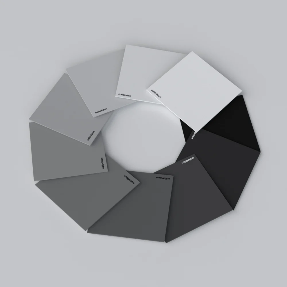
Classification by Reflectivity Level
Low Reflectance (2-30%)
- Typical values: 2%, 5%, 10%, 20%, 30%
- Applications:
- LiDAR dynamic range testing (minimum detectable signal)
- Dark object detection validation
- Low-light camera calibration
- Simulating asphalt, dark vehicle paint
- Materials: Carbon-loaded coatings, specialty black inks
Mid Reflectance (40-60%)
- Typical values: 40%, 50%, 60%
- Applications:
- General-purpose calibration
- Gray balance reference
- Multi-level intensity testing
- Simulating concrete, unpainted metal
- Materials: Gray ceramic, controlled pigment mixtures
High Reflectance (70-99%)
- Typical values: 70%, 80%, 90%, 95%, 99%
- Applications:
- Maximum range LiDAR testing
- Bright target detection
- Overexposure testing
- Simulating retroreflectors, white vehicles, road signs
- Materials: Barium sulfate, white ceramic, Spectralon®
Most Common Configuration: 10%, 50%, 90% three-target set covers the full dynamic range for most applications.
Classification by Wavelength Range
Visible Spectrum (400-780nm)
- DRS-R[XX]V Series
- Applications:
- RGB camera calibration
- Machine vision system setup
- Color measurement validation
- Industrial inspection
- Coating optimization: Balanced across red, green, blue wavelengths
Near-Infrared Extended (400-1100nm)
- DRS-R[XX]N Series
- Applications:
- NIR-sensitive industrial cameras
- Multispectral imaging
- Combined visible + NIR sensor systems
- Short-range LiDAR (850nm wavelength)
- Coating optimization: Spectral uniformity through visible and NIR
LiDAR-Specific (850-1550nm)
- DRS-R[XX]L Series
- Applications:
- Automotive LiDAR calibration (905nm, 1550nm)
- Long-range distance measurement validation
- ToF (Time-of-Flight) sensor testing
- Industrial laser ranging systems
- Coating optimization: Peak performance at common LiDAR wavelengths
Full Spectrum (200-2000nm)
- DRS-R[XX]F Series
- Applications:
- Research and development
- Spectrophotometry
- Multi-sensor fusion (camera + LiDAR + thermal)
- UV and NIR simultaneous testing
- Coating optimization: Broadband uniform response
Critical consideration: A visible-spectrum target may appear 50% reflective under white light but only 30% reflective at 905nm LiDAR wavelength. Always match your target’s spectral range to your sensor wavelength.
Classification by Substrate Material
Ceramic Substrate
- Advantages:
- Excellent dimensional stability
- High temperature resistance
- Superior flatness (±0.1mm across surface)
- Long-term durability
- Disadvantages:
- Higher cost
- Brittle (fragile if dropped)
- Limited to moderate sizes (<1m)
- Best for: Indoor laboratory calibration, precision metrology
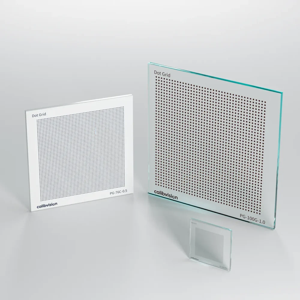
Glass Substrate
- Advantages:
- Exceptional flatness (±0.05mm)
- Transparent options for transmission testing
- Chemical resistance
- Easy to clean
- Disadvantages:
- Fragile
- Limited size options
- Expensive for large formats
- Best for: Optical bench setups, high-precision measurements
Aluminum Substrate
- Advantages:
- Lightweight yet rigid
- Large format capability (up to 3×5m)
- Weather-resistant with proper coating
- Mounting holes/brackets easily added
- Disadvantages:
- Thermal expansion (requires compensation)
- Surface preparation critical
- Potential oxidation without proper treatment
- Best for: Outdoor LiDAR testing, large-scale automotive validation
ABS/Composite Substrate
- Advantages:
- Cost-effective
- Lightweight
- Impact-resistant
- Easy to manufacture in custom shapes
- Disadvantages:
- Lower dimensional stability
- Temperature sensitivity
- Limited lifespan outdoors
- Lower precision (±5% typical)
- Best for: Educational use, preliminary testing, robotic vacuums
Film/Flexible Substrate
- Advantages:
- Rollable for transport
- Very large sizes possible
- Lowest cost per area
- Disadvantages:
- Requires rigid backing for use
- Poor flatness unless mounted
- Accuracy compromised by wrinkles
- Shortest lifespan
- Best for: Temporary setups, very large background targets
Classification by Size
Small Format (A6 to A4: 105mm – 297mm)
- Applications:
- Desktop testing
- Close-range calibration (<2m)
- Laboratory work
- Component-level validation
- Typical models:
- DRS-R50V-A6 (105×148mm)
- DRS-R90N-A5 (148×210mm)
- DRS-R10L-A4 (210×297mm)
Medium Format (A3 to 500mm: 297mm – 500mm)
- Applications:
- Mid-range testing (2-10m)
- Robotic vision systems
- Industrial inspection stations
- Sensor development
- Typical models:
- DRS-R50V-A3 (297×420mm)
- DRS-R90N-400×400
- DRS-R10L-500×500
Large Format (1m – 2m)
- Applications:
- Long-range LiDAR (10-50m)
- Automotive ADAS testing
- Outdoor validation
- Sensor fusion development
- Typical models:
- DRS-R50L-1000×1000
- DRS-R90L-1500×2000
Extra-Large Format (2m+)
- Applications:
- Highway-speed testing (50-300m)
- Long-range autonomous driving
- Military/aerospace applications
- Full-vehicle perception testing
- Typical models:
- DRS-XL50-2000×2500
- DRS-XL90-3000×4000
- DRS-XL10-3000×5000 (max size)
Size selection rule of thumb: Target should subtend at least 2° of the sensor’s field of view. For a sensor with 25° horizontal FOV testing at 50m distance, minimum target width = 50m × tan(2°) = 1.75m.
Specialty Configurations
Combination LiDAR-Camera Fusion Targets
- DRS-F Series
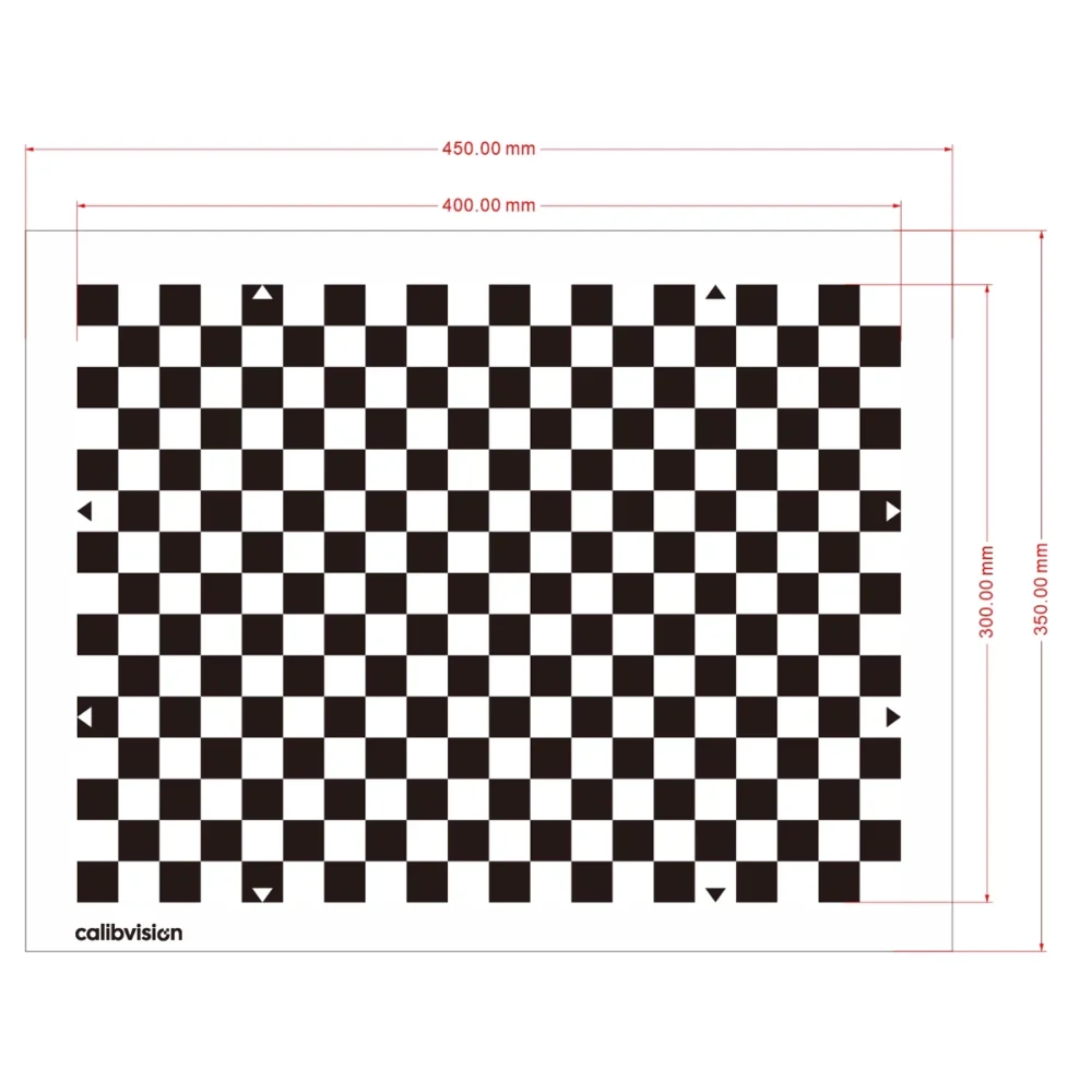
- Combines calibrated reflectance zones with geometric patterns (ChArUco, circles)
- Enables simultaneous calibration of camera intrinsics and LiDAR-camera extrinsics
- Available in ABS (indoor) or aluminum (outdoor) substrates
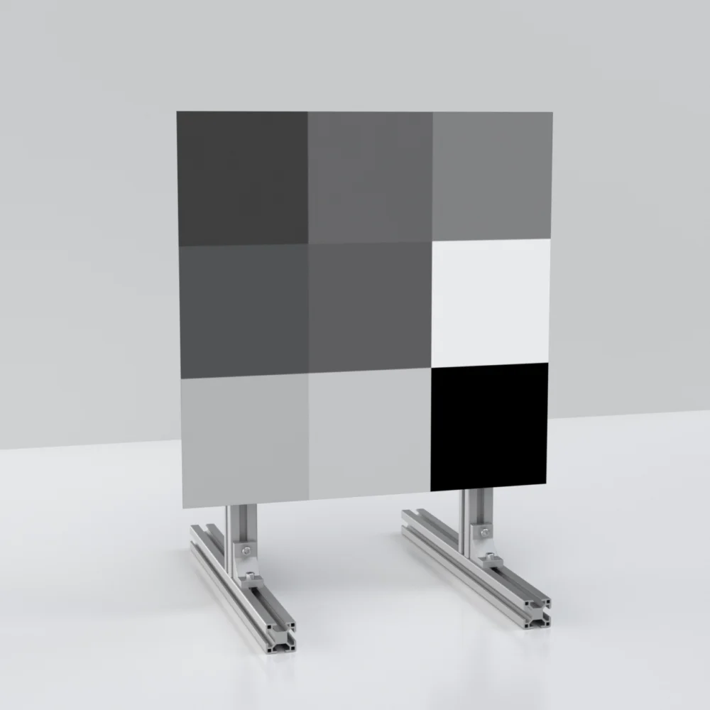
Multi-Level Gradient Targets
- Single target with multiple reflectance zones (e.g., 10%, 30%, 50%, 70%, 90%)
- Compact alternative to multi-target setups
- Useful for automated testing sequences
Custom Reflectivity Targets
- Any reflectance from 2-99% upon request
- Application examples:
- Matching specific road surface reflectance
- Simulating branded vehicle colors
- Replicating environmental conditions (wet road, snow)
Comparison Table: Target Types
| Target Type | Accuracy | Cost | Wavelength Range | Max Size | Durability | Best Application |
|---|---|---|---|---|---|---|
| Ceramic Substrate | ±1% | $$$$ | 200-2000nm | 500mm | Excellent | Lab calibration |
| Glass Substrate | ±0.5% | $$$$$ | 200-2000nm | 300mm | Good | Precision metrology |
| Aluminum Substrate | ±2% | $$$ | 400-1550nm | 5000mm | Excellent | Outdoor LiDAR |
| ABS Composite | ±5% | $$ | 400-1100nm | 1000mm | Good | Indoor testing |
| Film/Flexible | ±10% | $ | 400-780nm | Unlimited | Poor | Backgrounds only |
→ Learn more: Reflectance Standards Comparison Guide: Which Type Should You Use?
<a name=”applications”></a>
5. Applications in LiDAR Testing
Diffuse reflectance standards have become indispensable in modern autonomous systems development. Here’s how they’re used across industries.
Automotive LiDAR Calibration
Challenge: Automotive LiDAR sensors must reliably detect objects from 0.5m (pedestrian near vehicle) to 300m (highway obstacle detection) under varying lighting, weather, and surface conditions. Intensity calibration ensures the sensor correctly interprets reflectance values, distinguishing between a dark-clothed pedestrian (10-15% reflectance) and a white truck (80-90% reflectance).
Testing Procedure:
Step 1: Range Calibration
- Position 90% reflectance standard at known distances (5m, 10m, 25m, 50m, 100m, 200m)
- Verify measured distance matches actual distance within specification (typically ±2cm)
- Repeat with 50% and 10% targets to validate across reflectivity levels
Step 2: Intensity Calibration
- Fix distance (e.g., 50m)
- Measure intensity return from 10%, 30%, 50%, 70%, 90% reflectance standards
- Verify intensity ratios match expected values
- Example: 90% target should return 9× the intensity of 10% target
Step 3: Dynamic Range Validation
- Determine maximum detection range for each reflectivity level
- Verify no saturation at close range with high-reflectance targets
- Confirm minimum detectable reflectance at maximum specified range
Step 4: Angular Response Testing
- Rotate target from 0° to ±60° relative to LiDAR beam
- Verify intensity follows Lambertian cosine law (or document deviations)
- Identify any angular dead zones or anomalies
Real-World Case Study: A Tier-1 automotive supplier developing a 200m-range LiDAR for highway autonomy discovered their sensor over-estimated distances to low-reflectance targets by 3-5% at >100m range. Using DRS-R10L and DRS-R50L targets, they calibrated a reflectance-dependent correction algorithm, reducing distance error to <1% across the full operational envelope.
Camera-LiDAR Sensor Fusion
Challenge: Autonomous vehicles fuse data from cameras (providing texture, color, signs) and LiDAR (providing precise 3D geometry). Misalignment between these sensors—even by 1-2cm or 0.5°—causes object detection errors.
Calibration Approach: Traditional methods calibrate cameras and LiDAR separately, then estimate extrinsic transform. Modern approach uses combination targets:
DRS-F Series Fusion Targets feature:
- Geometric patterns (ChArUco boards, circles) for camera calibration
- Surrounding calibrated reflectance zones for LiDAR detection
- Same rigid substrate ensures both sensors see identical geometry
Procedure:
- Camera detects ChArUco corners, solves for intrinsic parameters and pose
- LiDAR detects reflectance zone boundaries, calculates 3D positions
- Algorithm solves for LiDAR-camera extrinsic transform by matching 2D camera pixels to 3D LiDAR points
- Single-shot calibration—no need to move target or switch setups
Advantage over sequential calibration:
- Eliminates accumulated error from separate measurements
- Faster workflow (one target vs. two separate procedures)
- Guaranteed spatial correspondence between camera and LiDAR measurements
Long-Distance LiDAR Ranging
Challenge: Highway autonomous driving requires detecting obstacles at 150-300m. At these distances:
- Signal-to-noise ratio is poor (inverse square law)
- Atmospheric effects become significant
- Small targets are difficult to resolve
Testing Requirements: Must validate that the LiDAR can detect a low-reflectance object (pedestrian ≈15%, dark vehicle ≈10%) at maximum claimed range.
Setup:
- DRS-XL10-3000×4000 (3m × 4m, 10% reflectance) positioned at 200m
- Simulates worst-case scenario: dark object at long range
- Target size ensures sufficient LiDAR points hit surface (at 200m, 0.1° beam divergence yields ~35cm spot size; 3×4m target captures multiple returns)
Validation Criteria:
- ≥5 valid point returns per scan
- Range measurement within ±5cm
- Intensity reading clearly above noise floor
- Consistent detection across 100 consecutive scans
Outdoor Testing Considerations:
- Time of day (solar angle affects atmospheric scattering)
- Weather (rain reduces range by 20-40%)
- Temperature (thermal shimmer at >30°C distorts long-range returns)
Calibvision’s DRS-XL series uses aluminum substrates with waterproof coatings, enabling outdoor testing in light rain and full sunlight without degradation.
Robotic Vision Systems
Industrial AGVs (Automated Guided Vehicles): Factory robots navigate using 2D LiDAR or time-of-flight sensors. Reflectance standards validate:
- Floor/obstacle discrimination (shiny warehouse floors ≈70%, cardboard boxes ≈40%)
- Cliff detection (avoiding loading docks, stairs)
- Dynamic obstacle response time
Robotic Vacuum Cleaners: Consumer robots use lower-cost optical sensors (850nm LEDs + photodiodes). Testing requires:
- DRS-R Series in multiple reflectivities (10%, 50%, 90%)
- Small format (A6, A5 sufficient for <2m range)
- Visible + NIR wavelength coverage (many robots use white LEDs + NIR for different sensing modes)
Validation:
- Minimum detectable obstacle (10% reflectance at 15cm)
- Cliff detection threshold (transition from 50% carpet to 0% air gap)
- False positive rate on shiny floors (90% reflectance shouldn’t trigger as obstacle)
Aerospace & Defense
Military LiDAR Applications:
- Aircraft landing system calibration (runway detection in fog)
- Missile guidance system testing (target acquisition and tracking)
- Reconnaissance drone sensors (ground texture mapping)
Requirements:
- Classified reflectance values matching specific targets (vehicles, buildings)
- Extremely large targets (10m+) for aircraft testing at operational altitudes
- Multi-spectral (visible, NIR, SWIR) for different sensor combinations
- Extreme environmental stability (-40°C to +60°C, saltwater exposure)
Research & Development
Academic Research:
- Algorithm development (testing new LiDAR processing techniques)
- Sensor characterization (measuring BRDF, SNR, linearity)
- Materials science (measuring reflectance of new coatings)
Requirements:
- Certified calibration with full measurement uncertainty budget
- NIST/NIM traceability
- Multiple reflectance levels (5+ targets typical)
- Custom wavelengths (UV, visible, NIR, SWIR, MWIR)
Example: MIT researchers studying LiDAR performance in snow used custom 95% reflectance standards to simulate fresh snow (90-95% reflective) and 30% standards to simulate wet asphalt under snowmelt.
Emerging Applications
Drone Navigation: Small UAVs use lightweight LiDAR for obstacle avoidance. Testing requires portable, lightweight targets.
Smart City Infrastructure: Traffic monitoring systems use LiDAR to count vehicles and classify by size. Calibration ensures accurate counts regardless of vehicle color.
Agricultural Robotics: Autonomous tractors and harvesters use LiDAR + cameras for crop row detection. Reflectance standards validate performance on varying soil/vegetation reflectances.
→ Learn more: LiDAR Calibration Guide: Step-by-Step Procedures Using Reflectance Standards
<a name=”specifications”></a>
6. Key Specifications to Consider
Selecting the right diffuse reflectance standard requires understanding critical specifications. Here’s what matters—and why.
Specification #1: Reflectance Accuracy
Definition: The maximum deviation between the target’s actual reflectance and its nominal value.
Common Accuracy Grades:
| Grade | Accuracy | Typical Cost | Applications |
|---|---|---|---|
| Research | ±0.5% | $$$$$ | Metrology, standards labs |
| Professional | ±1-2% | $$$-$$$$ | Automotive, aerospace |
| Industrial | ±3-5% | $$-$$$ | Manufacturing QC |
| Commercial | ±5-10% | $-$$ | Education, rough testing |
Why it matters: A 50% nominal target with ±5% accuracy could actually be anywhere from 45-55%. In LiDAR intensity calibration, this 10-percentage-point uncertainty could cause:
- Misclassification of pedestrians vs. background
- False object detection or missed detections
- Incorrect distance estimates (intensity-based ranging algorithms)
Calibvision DRS Series: ±2% accuracy across all standard models, ±1% available for premium ceramic substrates.
How to verify: Calibration certificate should include:
- Measured reflectance at multiple wavelengths (not just a single number)
- Measurement uncertainty budget (per ISO GUM guidelines)
- Traceability statement (NIST, or equivalent national lab)
- Calibration date and recommended re-cal interval
Specification #2: Spectral Range & Uniformity
Why wavelength matters:
Many materials are “spectrally selective”—they reflect different amounts at different wavelengths:
Example: White Paint
- 450nm (blue): 85% reflectance
- 550nm (green): 88% reflectance
- 650nm (red): 87% reflectance
- 905nm (NIR): 45% reflectance ⚠️
This paint appears white to human eyes but is dark gray to a 905nm LiDAR—disastrous for calibration.
Spectral Uniformity Specification:
Quality reflectance standards specify maximum deviation across their wavelength range:
- Excellent: <2% variation 400-1100nm
- Good: <5% variation 400-1100nm
- Poor: >10% variation (avoid for NIR/LiDAR use)
Match your sensor wavelength:
| Your Sensor | Required Spectral Range | Recommended Target |
|---|---|---|
| RGB camera | 400-700nm | DRS-R[XX]V (visible) |
| Monochrome industrial camera | 400-900nm | DRS-R[XX]N (NIR extended) |
| 850nm LiDAR (short-range) | 800-900nm | DRS-R[XX]N or DRS-R[XX]L |
| 905nm LiDAR (automotive) | 850-950nm | DRS-R[XX]L (LiDAR-specific) |
| 1550nm LiDAR (long-range) | 1500-1600nm | DRS-R[XX]L (LiDAR-specific) |
| Multi-spectral system | 400-2000nm | DRS-R[XX]F (full spectrum) |
Pro tip: If testing a 905nm LiDAR, request calibration certificate showing measured reflectance specifically at 905nm, not just “average across 850-950nm band.”
Specification #3: Lambertian Conformity
Definition: How closely the target’s angular response matches ideal Lambertian behavior.
Measurement: Lambertian conformity is typically measured as the deviation from ideal across ±60° viewing angle:
Lambertian Conformity = 100% – (max deviation from ideal / ideal) × 100%
Example:
- Ideal Lambertian: Intensity at 60° = cos(60°) × I₀ = 0.50 × I₀
- Measured target: Intensity at 60° = 0.48 × I₀
- Deviation: (0.50 – 0.48) / 0.50 = 4%
- Lambertian conformity: 100% – 4% = 96% ✓
Quality Grades:
| Conformity | Quality | Suitability |
|---|---|---|
| >98% | Excellent | Research, metrology |
| 95-98% | Very Good | Automotive, aerospace |
| 90-95% | Good | Industrial testing |
| 80-90% | Fair | Non-critical applications |
| <80% | Poor | Avoid for LiDAR calibration |
Why it matters: LiDAR sensors rarely hit targets perfectly perpendicular. Real-world scenarios:
- Vehicle LiDAR mounted at angle scanning road-level targets
- Robotic arm-mounted sensor viewing workspace at varying angles
- Handheld scanning devices with non-perpendicular orientation
Poor Lambertian conformity means measured intensity varies unpredictably with angle—impossible to calibrate reliably.
Calibvision DRS Series: >95% Lambertian conformity across ±60°, with angular response curve provided in calibration certificate.
Specification #4: Size Requirements
Size depends on three factors:
1. Testing Distance
At distance D, a sensor with angular resolution θ resolves a spot size:
Spot diameter = D × tan(θ)
Your target must be larger than the spot size. General rule: Target size ≥ 3× spot diameter (to ensure most signal comes from uniform reflectance area).
Example:
- LiDAR: 0.1° beam divergence, testing at 100m
- Spot size: 100m × tan(0.1°) = 0.17m = 17cm
- Minimum target size: 3 × 17cm = 51cm (use ≥500×500mm target)
2. Sensor Field of View
For full-field calibration, target should subtend significant portion of FOV:
Recommended: Target subtends 2-10° of sensor FOV
Example:
- Camera: 60° horizontal FOV, testing at 5m
- 10° subtended angle requires target width: 5m × tan(10°) = 0.88m
- Recommendation: 1000×750mm (A0 size or custom)
3. Multi-Point Return Requirements
Some LiDAR processing algorithms require multiple points to hit the target:
- Minimum: 4 points (defines a plane)
- Better: 9+ points (enables outlier rejection)
- Best: 25+ points (statistical validation)
At maximum range, sensor spatial resolution degrades. Calculate points per target:
Points per scan = (Target width / Spot size) × (Target height / Spot size)
Size Selection Chart:
| Testing Distance | Small Object (50mm) | Medium Object (300mm) | Large Object (2000mm) |
|---|---|---|---|
| 0.5m | A6 (105mm) | A5 (148mm) | A4 (210mm) |
| 2m | A5 (148mm) | A4 (210mm) | A3 (297mm) |
| 10m | A4 (210mm) | 500×500mm | 1000×1000mm |
| 50m | 500×500mm | 1000×1000mm | 2000×3000mm |
| 200m | 1500×2000mm | 2000×3000mm | 3000×5000mm |
Specification #5: Environmental Stability
Temperature Coefficient:
Reflectance changes with temperature due to:
- Thermal expansion (changes surface microstructure)
- Material properties (some pigments temperature-sensitive)
Specification format: ΔR / ΔT (reflectance change per °C)
Quality grades:
- Excellent: <0.01% per °C (±0.5% over -20°C to +60°C range)
- Good: <0.02% per °C (±1.6% over range)
- Acceptable: <0.05% per °C (±4% over range)
Humidity Effects:
Water absorption can alter reflectance:
Quality grades:
- Excellent: <1% change at 85% RH
- Good: <2% change at 85% RH
- Acceptable: <5% change at 85% RH
UV Stability:
Outdoor targets must resist UV degradation:
Testing standard: ASTM G154 (UV lamp exposure)
Quality grades:
- Excellent: <1% change after 2000 hours
- Good: <3% change after 1000 hours
- Acceptable: <10% change after 500 hours
Calibvision DRS Series – Environmental Specs:
- Temperature: <1% change, -20°C to +60°C
- Humidity: <2% change at 85% RH
- UV: <3% change after 1000 hours
- Waterproof: IP65-equivalent coating (suitable for outdoor testing)
Specification #6: Certification & Traceability
Why Traceability Matters:
Without traceability to national/international standards, you cannot prove:
- Target meets claimed specifications
- Measurements are comparable to other labs
- Compliance with automotive/aerospace standards
Traceability Chain:
- National Metrology Institute (NIST, NPL)
- Maintains primary standards
- Publishes reference values
- Calibration Laboratory (ISO 17025 accredited)
- Calibrates working standards against primary standards
- Issues certificates with measurement uncertainty
- Manufacturer (Calibvision)
- Measures production units against working standards
- Issues certificates traceable to Step 2
- End User (You)
- Receives target with calibration certificate
- Uses for device calibration
Required Certificate Contents:
✓ Unique serial number ✓ Measurement date ✓ Measurement conditions (temperature, humidity) ✓ Reflectance values at specified wavelengths ✓ Measurement uncertainty (±X%, k=2, 95% confidence) ✓ Traceability statement (“traceable to NIST through…”) ✓ Recommended re-calibration interval ✓ Calibration lab accreditation number (ISO 17025)
Re-Calibration Intervals:
Recommended frequency depends on use:
| Usage | Interval |
|---|---|
| Critical safety (automotive) | 12 months |
| Industrial QC | 24 months |
| General testing | 36 months |
| Occasional lab use | 36-60 months |
Or re-calibrate whenever:
- Target shows visible damage
- Stored in harsh environment
- Dropped or impacted
- Measurement results seem inconsistent
Cost consideration: Re-calibration typically costs 30-50% of new target price. For multi-target setups, budget for annual re-cal costs.
Specification #7: Substrate Material
Covered in Section 4 (Types), but key selection factors:
Choose Ceramic if:
- Indoor use only
- Maximum dimensional stability needed
- Small/medium sizes acceptable
- Budget allows
Choose Aluminum if:
- Outdoor testing required
- Large sizes needed (>1m)
- Need mounting holes/brackets
- Weather resistance critical
Choose ABS if:
- Cost-sensitive application
- Educational/demonstration use
- Indoor only
- Accuracy ±5% acceptable
Avoid Film/Flexible if:
- Any precision required
- Target will be moved frequently
- Outdoor use
→ Learn more: How to Choose Diffuse Reflectance Standards: Complete Buyer’s Guide
<a name=”manufacturing”></a>
7. Manufacturing Standards & Quality
Not all reflectance standards are created equal. Manufacturing quality directly impacts calibration accuracy and long-term stability. Here’s what separates professional-grade from consumer-grade targets.
The Problem with Low-Cost Targets
Contamination During Manufacturing:
Generic calibration targets are often produced in uncontrolled environments:
- Dust particles embedded in surface (causes bright spots)
- Fingerprints from handling (creates non-uniform areas)
- Airborne contaminants (fibers, pollen) trapped in coating
- Inconsistent coating thickness (streaks, color variations)
Real-world impact: A single 100μm dust particle on a surface can shift local reflectance by 5-10%. Multiply by dozens of particles across the target, and calibration becomes unreliable.
Edge Sharpness Issues:
For combination targets (reflectance zones + geometric patterns):
- Printed targets: Ink bleeds, creating soft edges (±0.5mm transition zone)
- Low-quality photolithography: Undercutting, rough edges (±0.2mm)
- High-quality laser etching: Sharp transitions (<0.05mm)
Why edges matter: Sub-pixel edge detection algorithms (used in camera calibration) require sharp, high-contrast transitions. Soft edges introduce systematic errors in corner detection → camera calibration → ultimately affects camera-LiDAR fusion accuracy.
Cleanroom Photolithography Process
Calibvision’s Manufacturing Approach:
Step 1: Substrate Preparation (ISO Class 7 Cleanroom)
- Precision-cut ceramic, glass, or aluminum substrate
- Multi-stage cleaning: ultrasonic bath, deionized water rinse, plasma treatment
- Flatness verification: laser interferometry (±0.1mm tolerance)
- Result: Contamination-free, molecularly clean surface
Step 2: Coating Application (ISO Class 6 Cleanroom)
- Proprietary matte ink formulation (optimized for spectral uniformity)
- Controlled application: doctor blade or spray coating in sealed chamber
- Thickness control: ±5μm across entire surface
- Drying: Controlled temperature/humidity profile prevents defects
- Result: Uniform, defect-free diffuse coating
Step 3: Pattern Definition (Laser Etching) For combination targets with geometric features:
- CO₂ or fiber laser engraving (±10μm position accuracy)
- Depth control: removes coating without damaging substrate
- Edge sharpness: <0.05mm transition width
- Result: Crisp, high-contrast patterns for camera calibration
Step 4: Curing & Stabilization
- Thermal cycling (accelerates coating stabilization)
- UV pre-exposure (minimizes future degradation)
- Humidity conditioning
- Result: Stable reflectance properties (ready to use)
Step 5: Quality Control Every target undergoes:
- Visual inspection (100×): No defects >50μm
- Reflectance measurement (spectrophotometer): Verify uniformity across surface (<2% variation)
- Lambertian conformity test: Verify angular response (±60° scan)
- Dimensional verification: Flatness, squareness within tolerance
- Result: Only targets meeting specs proceed to calibration
Step 6: Calibration (ISO 17025 Lab)
- Multi-wavelength spectrophotometry (400-2000nm, 50nm intervals)
- Angular response characterization (0°, ±15°, ±30°, ±45°, ±60°)
- Environmental testing (temperature/humidity effects documented)
- Certificate generation with measurement uncertainty
- Result: Fully characterized, certified reflectance standard
Quality Cost Tradeoff:
| Manufacturing Aspect | Consumer Grade | Professional Grade | Cost Impact |
|---|---|---|---|
| Environment | Open factory | ISO 6/7 cleanroom | +30% |
| Coating Process | Manual brush/spray | Controlled deposition | +20% |
| Substrate Prep | Basic cleaning | Multi-stage precision | +15% |
| Pattern Creation | Printing | Laser etching | +25% |
| QC Testing | Visual only | Spectrophotometric | +40% |
| Calibration | None or basic | ISO 17025 traceable | +50% |
| Total Cost | $ | $$$ (3-4× consumer) | Justified by reliability |
How to Verify Quality When Purchasing
Red Flags (Avoid These Suppliers):
❌ No calibration certificate included
❌ Certificate lacks measurement uncertainty
❌ No traceability statement
❌ Visible surface defects (dust, scratches, color variations)
❌ Reflectance specified as single number (no wavelength curve)
❌ No Lambertian conformity data
❌ “Calibrated in-house” (without ISO 17025 accreditation)
❌ Unrealistically low prices (if it’s 1/5 the market price, there’s a reason)
Green Flags (Quality Indicators):
✓ Full spectral calibration curve provided
✓ NIST traceability explicitly stated
✓ Measurement uncertainty budget included (per ISO GUM)
✓ Lambertian conformity >95% ✓ Environmental stability data provided
✓ Cleanroom manufacturing mentioned
✓ ISO 17025 calibration lab accreditation
✓ Recommended re-calibration interval stated
✓ Physical inspection shows no defects
✓ Manufacturer has presence in automotive/aerospace industry
Questions to Ask Suppliers:
- “What’s your Lambertian conformity across ±60°?”
- If they don’t know: ⚠️ Warning sign
- “Can you provide spectral reflectance at [your sensor’s wavelength]?”
- If they only offer “broadband” or “visual” values: ⚠️ Problem
- “What’s the measurement uncertainty at 95% confidence?”
- If answer is vague or missing: ❌ Not properly calibrated
- “Is your calibration lab ISO 17025 accredited?”
- If no: ❌ Not traceable to national standards
- “What cleanroom class is your manufacturing environment?”
- If not cleanroom at all: ⚠️ Contamination risk
Long-Term Stability & Durability
Expected Lifespan:
| Substrate Type | Indoor Use | Outdoor Use |
|---|---|---|
| Ceramic | 10+ years | Not recommended |
| Glass | 10+ years | 5-7 years (with UV protection) |
| Aluminum (coated) | 8-10 years | 5-10 years |
| ABS | 5-7 years | 2-3 years |
| Film | 2-3 years | <1 year |
Degradation Modes:
- UV Exposure: Breaks down organic binders in coatings
- Prevention: UV-resistant coatings, indoor storage when not in use
- Mechanical Wear: Handling, cleaning, transport
- Prevention: Protective cases, white gloves, careful cleaning protocols
- Environmental: Temperature cycling, humidity, pollutants
- Prevention: Climate-controlled storage, waterproof coatings
- Chemical: Cleaners, solvents, acidic/basic environments
- Prevention: Use only approved cleaning methods (mild soap, water, IPA)
Maintenance Best Practices:
✓ Store in protective case when not in use ✓ Clean only with lint-free cloth + isopropyl alcohol (IPA) ✓ Never touch surface with bare hands (use nitrile gloves) ✓ Avoid stacking targets (scratching risk) ✓ Store in climate-controlled environment (20-25°C, 40-60% RH) ✓ Annual visual inspection for damage ✓ Re-calibrate per manufacturer recommendation
→ Learn more: Why Manufacturing Quality Matters: Cleanroom vs Conventional Targets
8. How to Choose the Right Reflectance Standard
Selecting the optimal diffuse reflectance standard for your application involves balancing technical requirements, budget, and practical considerations. Here’s a systematic approach.
Step 1: Define Your Application Requirements
Question 1: What are you calibrating?
- LiDAR sensor → Need LiDAR-specific wavelength (DRS-L series)
- RGB camera → Visible spectrum sufficient (DRS-V series)
- NIR industrial camera → Extended spectrum 400-1100nm (DRS-N series)
- Multi-sensor system → Full spectrum or multiple targets (DRS-F series)
Question 2: What wavelength(s)?
Find your sensor’s operating wavelength:
- RGB camera: 400-700nm
- Monochrome camera: Check sensor datasheet (often 400-900nm)
- LiDAR: 850nm, 905nm, 940nm, or 1550nm (check datasheet)
- ToF sensor: Usually 850nm or 940nm
- Multispectral: Multiple wavelengths specified
Match target spectral range to sensor wavelength +/- 50nm minimum.
Question 3: What testing distance?
Measure the farthest distance you’ll test:
- Desktop/lab: <2m → Small format (A6-A4)
- Industrial station: 2-10m → Medium format (A3-500mm)
- Autonomous vehicle: 10-50m → Large format (1-2m)
- Highway testing: >50m → Extra-large format (2m+)
Use sizing formula: Target size ≥ 3× (Distance × tan(Beam Divergence))
Question 4: Indoor or outdoor testing?
- Indoor only → Ceramic or ABS substrates acceptable
- Outdoor required → Aluminum substrate with waterproof coating
- Both → Aluminum for versatility
Question 5: Accuracy requirements?
- Research/metrology: ±0.5-1% (ceramic substrate, premium calibration)
- Automotive/aerospace: ±1-2% (standard professional grade)
- Industrial QC: ±3-5% (good for most applications)
- Education/demos: ±5-10% (budget-friendly options)
Automotive safety systems typically require ±2% or better.
Question 6: How many reflectivity levels?
- Single-point check: One target (usually 50%)
- Dynamic range test: Three targets (10%, 50%, 90%) – most common
- Full characterization: Five targets (10%, 30%, 50%, 70%, 90%)
- Specific application: Custom reflectivity matching real-world object
Step 2: Use Decision Flowchart
START
  |
  ├─ Sensor Type?
  |   ├─ LiDAR → What wavelength?
  |   |   ├─ 850nm / 905nm / 1550nm → DRS-L Series
  |   |
  |   ├─ Camera → What spectrum?
  |   |   ├─ Visible (RGB) → DRS-V Series
  |   |   ├─ Visible + NIR → DRS-N Series
  |   |
  |   ├─ Camera + LiDAR Fusion → DRS-F Series
  |
  ├─ Testing Distance?
  |   ├─ <2m → A6 / A5 / A4
  |   ├─ 2-10m → A3 / 400×400 / 500×500
  |   ├─ 10-50m → 1000×1000 / 1500×2000
  |   ├─ >50m → 2000×3000 / 3000×5000 (XL Series)
  |
  ├─ Environment?
  |   ├─ Indoor → Ceramic / ABS
  |   ├─ Outdoor → Aluminum
  |
  ├─ Accuracy Needs?
  |   ├─ ±0.5-1% → Premium ceramic
  |   ├─ ±1-2% → Standard professional
  |   ├─ ±3-5% → Industrial grade
  |
  └─ Budget?
      ├─ Research budget → Full 5-target set + re-cal plan
      ├─ Development budget → 3-target set (10%, 50%, 90%)
      ├─ Limited budget → Single 50% target + plan to upgrade
Step 3: Common Application Recommendations
Application: Automotive LiDAR (905nm, 200m range)
Recommended Setup:
- DRS-R10L-2000×3000 (low reflectance, large, for max range testing)
- DRS-R50L-1000×1000 (mid reflectance, general testing)
- DRS-R90L-1000×1000 (high reflectance, near-range saturation testing)
- Substrate: Aluminum (outdoor use)
- Budget: $3,000-5,000 for 3-target set
- Re-calibration: Annual (safety-critical application)
Application: Robotic Vacuum (850nm ToF, 3m range)
Recommended Setup:
- DRS-R10N-A5 (dark obstacle detection)
- DRS-R50N-A5 (general testing)
- DRS-R90N-A5 (bright surface / false positive testing)
- Substrate: ABS (cost-effective, indoor only)
- Budget: $400-600 for 3-target set
- Re-calibration: 2-3 years
Application: Industrial Inspection Camera (monochrome, 400-900nm, 1m working distance)
Recommended Setup:
- DRS-R50N-A4 (primary gray reference)
- Optional: DRS-R20N-A4 and DRS-R80N-A4 (extended dynamic range)
- Substrate: Ceramic (precision, stable)
- Budget: $500-800 for single target
- Re-calibration: 2 years
Application: Camera-LiDAR Fusion Development (905nm LiDAR + RGB camera)
Recommended Setup:
- DRS-F50NC-600×450 (combination target, 50% reflectance, NIR + visible, ChArUco pattern)
- Substrate: Aluminum (outdoor testing capability)
- Budget: $800-1,200
- Re-calibration: 18 months
Application: Research Lab (multi-wavelength spectrophotometry)
Recommended Setup:
- DRS-R Series in 10%, 30%, 50%, 70%, 90%, 99% (full dynamic range)
- Spectral range: Full spectrum (200-2000nm) – DRS-F suffix
- Size: A4 or A5 (compact for optical bench)
- Substrate: Ceramic (maximum stability)
- Budget: $3,000-6,000 for 6-target set
- Re-calibration: Annually (research publications require traceable calibration)
Step 4: Budget Planning
Initial Investment:
| Configuration | Cost Range | Use Case |
|---|---|---|
| Single target (50%) | $200-800 | Basic validation |
| 3-target set (10/50/90) | $500-2,500 | Most applications |
| 5-target set (10/30/50/70/90) | $1,200-4,500 | Full characterization |
| Large outdoor set (XL series) | $2,000-8,000 | Automotive long-range |
| Custom combination target | $800-2,000 | Sensor fusion |
Ongoing Costs:
- Re-calibration: 30-50% of purchase price
- Frequency: 1-3 years depending on application
- Storage/cases: $50-200 per target
- Maintenance (cleaning supplies): $50/year
Total Cost of Ownership (5 years):
Example: Automotive LiDAR Testing
- Initial: 3-target large format set = $4,000
- Re-cal (annual): $1,200 × 5 years = $6,000
- Storage/maintenance: $500
- Total 5-year cost: $10,500 ($2,100/year amortized)
Cost-Benefit Consideration:
A single false detection by an improperly calibrated ADAS system could result in:
- Recall costs: $50M-500M (depending on units affected)
- Liability: Incalculable if safety incident occurs
- Reputation damage: Long-term brand impact
Investment in proper calibration targets: ~$10K over 5 years Risk reduction: $100M+ potential exposure
ROI is obvious for safety-critical applications.
Step 5: Supplier Evaluation Checklist
When comparing suppliers, verify:
☐ ISO 17025 calibration (not just “calibrated in-house”) ☐ NIST traceability explicitly stated ☐ Measurement uncertainty provided (±X%, k=2, 95% confidence) ☐ Spectral calibration curve (not just single-wavelength value) ☐ Lambertian conformity specified (>95% for professional use) ☐ Environmental stability data (temperature/humidity effects) ☐ Cleanroom manufacturing mentioned ☐ Warranty period (1 year minimum for professional grade) ☐ Re-calibration service available ☐ Technical support (phone/email responsiveness) ☐ Delivery time (stock vs. custom manufacturing) ☐ Return policy (if target doesn’t meet needs)
Step 6: Verify Before Purchase
Request from supplier:
- Sample calibration certificate (verify it includes everything you need)
- Spectral curve at your wavelength (confirm suitability)
- Photos of actual product (verify quality, finish)
- Dimensional drawing (if custom size needed)
- References (customers in your industry)
Questions to ask yourself:
- Will this target still meet my needs in 3 years? (Plan for product evolution)
- Do I need multiple sizes? (Consider purchasing as a set)
- Should I buy spare capacity? (Extra target for expedited re-cal rotation)
- What’s my re-calibration strategy? (Budget for ongoing costs)
→ Learn more: Complete Buyer’s Guide to Reflectance Standards
9. Common Mistakes to Avoid
Even experienced engineers make these errors when working with diffuse reflectance standards. Learn from others’ mistakes.
Mistake #1: Using Uncalibrated “Gray Cards”
The Problem: Photography gray cards claim “18% reflectance,” but:
- Not calibrated with spectrophotometer
- Reflectance varies ±5-10% between units
- Only valid in visible spectrum (400-700nm)
- Often has slight specular component (glossy finish)
Real-World Consequence: An automotive Tier-1 supplier used photo gray cards for LiDAR calibration during early development. When they switched to certified standards for final validation, they discovered their intensity calibration was off by 15% at 905nm. Required algorithm rework delayed product launch by 3 months.
Solution: Always use certified, traceable reflectance standards for any engineering application. Gray cards are fine for photography—not for LiDAR.
Mistake #2: Ignoring Wavelength Incompatibility
The Problem: Assuming a target’s visible appearance indicates NIR/LiDAR reflectance.
Example: White paint appears 85% reflective to the human eye but may be only 40% reflective at 905nm due to pigment absorption. Conversely, some materials appear gray (50%) visually but are 80% reflective in NIR.
Real-World Consequence: A robotics company calibrated their 850nm LiDAR using a “50% gray” target that was actually 72% reflective at 850nm. Their robots consistently over-estimated distances to gray objects, causing navigation errors.
Solution: Always check the calibration certificate for reflectance at your specific sensor wavelength ±50nm. If your LiDAR operates at 905nm, you need reflectance certified at 905nm—not “broadband” or “visible average.”
Mistake #3: Target Too Small for Testing Distance
The Problem: Undersizing target relative to test distance and sensor beam divergence.
Formula Violation: Sensor spot size at distance D = D × tan(θ)
If target is smaller than 3× spot size, significant signal comes from background rather than calibrated target → invalid measurement.
Example:
- LiDAR beam divergence: 0.2° (typical automotive)
- Testing distance: 100m
- Spot size: 100m × tan(0.2°) = 0.35m = 35cm
- Minimum target size: 3 × 35cm = 105cm
Using a 50×50cm target at 100m means only 22% of signal comes from the target; 78% from background. Measurement is contaminated.
Real-World Consequence: Autonomous vehicle developer tested maximum range using undersized targets. Passed internal validation, but failed third-party certification testing with properly sized targets—required sensor redesign.
Solution: Calculate required target size before purchasing. For long-range testing (>50m), invest in large-format targets (2m+). It’s expensive but necessary.
Mistake #4: Not Accounting for Environmental Conditions
The Problem: Outdoor testing without considering temperature/humidity/weather effects.
Temperature Effect: A target with 0.02% per °C temperature coefficient tested at:
- Morning (15°C): 50.0% reflectance
- Afternoon (35°C): 50.4% reflectance
- Error: 0.4% (may seem small, but doubles measurement uncertainty)
Humidity Effect: Some coatings absorb moisture, temporarily increasing reflectance by 2-5%. Testing on a dry day vs. after rain yields different results.
Sunlight Effect: Direct sunlight heats target surface 20-40°C above ambient, causing thermal distortion in large aluminum targets (warping affects flatness, changes return angles).
Real-World Consequence: Outdoor LiDAR testing in summer heat showed “sensor drift” that was actually target temperature effects. Months wasted troubleshooting sensor before root cause discovered.
Solution:
- Use targets rated for outdoor environmental conditions
- Record temperature/humidity during testing
- Allow target to thermally stabilize (30 minutes in test environment)
- Shield from direct sunlight during testing (use shade canopy)
- Apply environmental corrections per calibration certificate data
Mistake #5: Contaminating Target Surface
The Problem: Fingerprints, dust, dirt alter surface reflectance.
Impact:
- Single fingerprint: Localized 5-15% reflectance change
- Dust accumulation: 2-10% overall reduction (worse at NIR wavelengths)
- Cleaning damage: Scratches scatter light, reduce Lambertian conformity
Real-World Consequence: Lab targets stored uncovered accumulated dust over 6 months. Reflectance dropped from 50% to 43%. Researchers blamed sensor drift, eventually discovered contaminated targets.
Solution:
- Always handle with nitrile gloves (never bare hands)
- Store in protective case when not in use
- Clean only with lint-free cloth + isopropyl alcohol
- Inspect visually before each use (10× magnification recommended)
- Re-calibrate if target has been contaminated or cleaned multiple times
Mistake #6: Exceeding Target Lifespan
The Problem: Assuming targets last forever without re-calibration.
Degradation Mechanisms:
- UV exposure breaks down coatings (outdoor targets)
- Repeated thermal cycling causes micro-cracking
- Mechanical wear from handling/cleaning
- Environmental exposure (humidity, pollutants)
Typical Degradation Rate:
- Indoor ceramic targets: 0.5-1% per year
- Outdoor aluminum targets: 1-2% per year
- Film targets: 3-5% per year
After 3 years without re-cal, a 50% target might be 48% or 52%—outside tolerance for precision work.
Real-World Consequence: Aerospace contractor used targets for 5 years without re-calibration. Failed customer audit due to out-of-cal test equipment. All data collected during that period had to be repeated—$500K+ cost.
Solution:
- Track target usage (serial number, dates used)
- Follow manufacturer re-cal recommendations (typically 1-3 years)
- Budget for re-calibration in advance
- Keep spare set in rotation (send for re-cal while using spare)
- Visual inspection annually for damage/degradation
Mistake #7: Mixing Target Types in Comparison
The Problem: Comparing results from different target types/manufacturers without verification.
Example: Testing LiDAR with:
- Supplier A’s 50% target: Measured range = 180m
- Supplier B’s 50% target: Measured range = 165m
Are these consistent? You can’t tell without:
- Both targets calibrated by same lab
- Both measured at same wavelength (905nm)
- Both with similar Lambertian conformity
- Both at similar environmental conditions
Supplier A’s “50%” might be 52%, Supplier B’s might be 47% at 905nm—explaining the 15m range difference.
Solution:
- Use targets from single manufacturer for comparative testing
- If mixing manufacturers, verify both are NIST-traceable to same standard
- Cross-check with third-party verification target
- Document which target used for each test (traceability)
Mistake #8: Ignoring Lambertian Conformity
The Problem: Assuming all “diffuse” targets are equally Lambertian.
Poor Lambertian Conformity Symptoms:
- Measured intensity varies unpredictably with small angle changes
- Calibration works at perpendicular angles but fails at oblique angles
- Results inconsistent between test runs (slight target repositioning changes outcome)
Example: A target with 75% Lambertian conformity might show:
- 0° (perpendicular): 50% reflectance as expected
- 30° angle: 42% reflectance (should be 43.3% per cosine law)
- 60° angle: 22% reflectance (should be 25%)
These deviations cause systematic errors in angle-dependent algorithms.
Solution:
- Specify >95% Lambertian conformity for professional applications
- Request angular response data in calibration certificate
- Test conformity: Measure intensity at 0°, ±30°, ±60°; verify follows cosine law
- Avoid cheap targets with no Lambertian specification
Mistake #9: Inadequate Budget Planning
The Problem: Buying cheapest targets to save money upfront, costing more long-term.
Hidden Costs of Cheap Targets:
- More frequent re-calibration needed (poor stability)
- Time wasted troubleshooting measurement inconsistencies
- Potential project delays if target inadequacy discovered late
- Risk of product failures traced to poor calibration
False Economy Example:
- Option A: Buy $200 uncertified target
- Discover doesn’t meet needs after 6 months
- Project delayed while proper target sourced
- Total cost: $200 (wasted) + $1,000 (proper target) + $50K (delay cost) = $51,200
- Option B: Buy $1,000 proper target initially
- Total cost: $1,000
Solution:
- Budget for quality from the start
- Consider total cost of ownership (5-year view)
- Factor in re-calibration costs
- Remember: Cheap targets aren’t cheap if they cause project failure
→ Learn more: Common Mistakes in LiDAR Calibration and How to Avoid Them
<a name=”calibvision-drs”></a>
10. Calibvision DRS Series Overview
Calibvision’s DRS (Diffuse Reflectance Standards) product line provides precision-calibrated optical targets for the most demanding automotive, aerospace, and industrial applications.
Why Calibvision?
1. Cleanroom Manufacturing Every DRS target is manufactured in an ISO Class 6/7 cleanroom environment, eliminating contamination that compromises accuracy in conventional targets.
2. Full Spectral Coverage Unlike competitors limited to visible spectrum, Calibvision DRS targets are calibrated across 200-2000nm, covering:
- Visible (RGB cameras)
- Near-infrared (industrial cameras, short-range LiDAR)
- LiDAR wavelengths (850nm, 905nm, 1550nm)
3. Superior Lambertian Properties DRS targets achieve >95% Lambertian conformity across ±60° viewing angles—critical for angle-independent calibration.
4. NIST-Traceable Calibration Every target includes an ISO 17025 calibration certificate with:
- Spectral reflectance curve (50nm intervals)
- Measurement uncertainty (±2%, k=2, 95% confidence)
- Angular response data
- Environmental stability specifications
5. Outdoor Durability Waterproof coatings and weather-resistant aluminum substrates enable year-round outdoor testing—essential for automotive validation.
Product Line Overview
DRS-R Series: Standard Reflectance Standards
Precision optical targets with calibrated reflectance levels:
By Wavelength Range:
- DRS-R[XX]V: 400-780nm (Visible spectrum)
- DRS-R[XX]N: 400-1100nm (Visible + NIR extended)
- DRS-R[XX]L: 850-1550nm (LiDAR-specific)
- DRS-R[XX]F: 200-2000nm (Full spectrum)
Standard Reflectivity Levels:
- 10% (dark objects, low-return testing)
- 20%, 30%, 40% (custom dark ranges)
- 50% (mid-gray reference, most common)
- 60%, 70%, 80% (custom bright ranges)
- 90% (high-return testing, retroreflector simulation)
Standard Sizes:
- A6 (105×148mm) – Desktop/lab testing
- A5 (148×210mm) – Close-range calibration
- A4 (210×297mm) – Standard industrial use
- A3 (297×420mm) – Mid-range testing
- Custom sizes available up to 3×5m
Example Models:
- DRS-R50V-A4: 50% reflectance, visible spectrum, A4 size
- DRS-R10N-500×500: 10% reflectance, NIR extended, 500mm square
- DRS-R90L-1000×1000: 90% reflectance, LiDAR-specific, 1m square
Pricing: $400-2,000 depending on size and substrate
DRS-L Series: LiDAR Testing Targets
Optimized for automotive and industrial LiDAR calibration:
Key Features:
- Peak reflectance uniformity at 905nm and 1550nm wavelengths
- Large format options (up to 3×5m) for long-range testing
- Aluminum substrate with weatherproof coating
- Outdoor-rated (IP65 equivalent)
Example Models:
- DRS-R10L-2000×3000: Low-reflectance, 2×3m for maximum range testing
- DRS-R50L-1000×1000: Mid-gray, 1m square for general LiDAR cal
- DRS-R90L-1500×2000: High-reflectance, 1.5×2m for saturation testing
Pricing: $1,500-5,000 depending on size
DRS-F Series: Fusion Calibration Targets
Combined camera-LiDAR calibration in a single target:
Design:
- ChArUco or circle patterns for camera intrinsic calibration
- Surrounding calibrated reflectance zones for LiDAR detection
- Rigid substrate ensures geometric correspondence
Substrate Options:
- ABS: Cost-effective, indoor use
- Aluminum: Outdoor-rated, superior flatness
Example Models:
- DRS-F50VC-A4: 50% reflectance, visible, ChArUco, A4 size (indoor)
- DRS-F90NCA-600×450: 90% reflectance, NIR, ChArUco, aluminum (outdoor)
Pricing: $800-2,000 depending on size and substrate
DRS-XL Series: Extra-Large Format
For highway-speed autonomous vehicle testing:
Sizes: 2×2.5m, 3×4m, 3×5m (maximum) Substrate: Aluminum with reinforced backing Mounting: Adjustable bracket system with angle control Transport: Wheeled cart or protective flight case
Example Models:
- DRS-XL50-2000×2500: 2×2.5m, 50% reflectance
- DRS-XL90-3000×4000: 3×4m, 90% reflectance
- DRS-XL10-3000×5000: 3×5m, 10% reflectance (maximum size)
Pricing: $3,000-8,000 depending on size and reflectivity
DRS-Set Series: Multi-Target Calibration Kits
Pre-configured sets for complete dynamic range testing:
DRS-Set3-Standard:
- 10%, 50%, 90% reflectance
- Choice of wavelength range (V, N, or L)
- Choice of size (A4, A5, 500mm, 1m)
- Includes protective cases
- Pricing: $1,200-4,000 (15% savings vs. individual purchase)
DRS-Set5-Pro:
- 10%, 30%, 50%, 70%, 90% reflectance
- Full characterization kit
- Pricing: $2,500-7,000
DRS-Set-Custom:
- User-specified reflectivity levels
- Mixed sizes available
- Contact sales for quote
Calibration & Support
Included with Every Target:
- ISO 17025 calibration certificate
- Spectral reflectance curve
- Lambertian conformity data
- Measurement uncertainty statement
- Handling and care instructions
Re-Calibration Services:
- Annual or bi-annual re-cal available
- 2-week turnaround typical
- Loaner targets available during re-cal period
- Cost: 30-40% of original purchase price
Technical Support:
- Application engineering consultations
- Custom target design
- On-site calibration services (for large installations)
- Training workshops
Trusted by Industry Leaders
Calibvision DRS targets are used by:
- Leading automotive OEMs for ADAS validation
- Tier-1 suppliers for LiDAR sensor development
- Aerospace contractors for optical system testing
- Research institutions for photonics R&D
Certifications: Every target ships with a serial-numbered inspection report. Measurements are NIST/NIM-traceable; product-level traceability is accredited under CNAS L0579 and recognised internationally through ILAC-MRA. Independent third-party CNAS/ILAC calibration is available on request.
How to Order
Standard Products: Browse our online catalog at calibvision.com/products/diffuse-reflectance-standards
Custom Requirements: Contact our technical sales team:
- Email: sales@calibvision.com
- Web: calibvision.com/contact
Quote Request Information: Please provide:
- Application (LiDAR type, camera, etc.)
- Sensor wavelength(s)
- Testing distance
- Desired reflectivity levels
- Indoor or outdoor use
- Quantity needed
- Timeline
Delivery:
- Stock items: 1-2 weeks
- Custom sizes/reflectivity: 4-6 weeks
- Large format (XL series): 6-8 weeks
→ Shop DRS Series: Explore Calibvision’s Full Product Line
<a name=”faq”></a>
11. Frequently Asked Questions
Q1: What’s the difference between diffuse reflectance standards and photography gray cards?
A: Photography gray cards are uncalibrated consumer products designed for approximate visible-light use. Diffuse reflectance standards are precision optical instruments with:
- Spectrophotometer calibration (±2% accuracy vs. ±10% for gray cards)
- NIST-traceable certification
- Specified wavelength response (not just visual appearance)
- Lambertian surface properties (gray cards often have specular component)
- Environmental stability specifications
For any engineering application—especially LiDAR calibration—certified reflectance standards are essential. Gray cards are appropriate only for basic photography workflows.
Q2: Can I use a visible-spectrum target for NIR or LiDAR calibration?
A: No—this is a critical mistake. Many materials that appear gray (50% reflective) in visible light have dramatically different reflectance at NIR wavelengths (850nm, 905nm, 1550nm). Always use targets calibrated at your specific sensor wavelength.
Example: White paint typically reflects 85% in visible spectrum but only 40-50% at 905nm. Using a visible-only target for 905nm LiDAR calibration would cause 35+ percentage-point error.
Solution: Specify DRS-L (LiDAR-specific) or DRS-N (NIR-extended) targets and verify calibration certificate includes data at your wavelength.
Q3: What size reflectance standard do I need?
A: Target size depends on:
- Testing distance
- Sensor beam divergence
- Desired measurement confidence
Formula: Minimum target size = 3× (Distance × tan(Beam Divergence))
Example:
- LiDAR: 0.1° beam, testing at 50m
- Spot size: 50m × tan(0.1°) = 8.7cm
- Minimum target: 3 × 8.7cm = 26cm
- Recommendation: 500×500mm target (provides 5.7× margin)
Quick Reference:
- <2m distance: A6-A4 (105-297mm)
- 2-10m distance: A3-500mm
- 10-50m distance: 1-2m
- 50m distance: 2m+ (XL series)
Q4: How accurate should my reflectance standard be?
A: Depends on application:
- Safety-critical automotive: ±1-2% (required by most OEMs)
- Aerospace/defense: ±1-2%
- Industrial QC: ±3-5%
- Research: ±0.5-1%
- Education/demos: ±5-10%
Rule of thumb: Your target accuracy should be 3-5× better than your required measurement uncertainty.
If you need to measure reflectance to ±5%, use a target with ±1% accuracy or better.
Q5: Do I need NIST-traceable calibration?
A: For professional applications, yes:
Legally required:
- Automotive safety systems (ADAS, autonomous driving)
- Aerospace systems
- Medical devices
- Any system subject to regulatory approval
Strongly recommended:
- Published research (peer review often requires traceability)
- Customer-audited manufacturing (ISO certification)
- Multi-lab comparisons
Not strictly necessary:
- Internal product development (early stages)
- Educational demonstrations
- Hobby/personal projects
Benefit: Traceability ensures your measurements are comparable to others worldwide and defensible in audits/litigation.
Q6: How often should I re-calibrate?
A: Recommended intervals:
| Application Type | Interval | Rationale |
|---|---|---|
| Automotive safety | 12 months | Regulatory requirement |
| Aerospace | 12-24 months | Industry standard |
| Industrial QC | 24 months | Balance cost vs. accuracy |
| Research | 12-24 months | Publication credibility |
| General testing | 36 months | Cost-effective |
Also re-calibrate if:
- Target dropped or damaged
- Visible contamination/wear
- Stored in harsh environment (outdoor, hot, humid)
- Measurement results seem inconsistent
- Customer/regulator requires it
Cost: Typically 30-40% of original purchase price. Plan this into your budget.
Q7: Can reflectance standards be used outdoors?
A: Yes, if properly specified:
Required features for outdoor use:
- ✓ Aluminum substrate (not ceramic or ABS)
- ✓ Waterproof coating (IP65 equivalent)
- ✓ UV-resistant materials
- ✓ Temperature stability specification (-20°C to +60°C)
Handling outdoor testing:
- Allow target to stabilize to ambient temperature (30 min)
- Shield from direct sunlight during measurement (use shade canopy)
- Record temperature/humidity conditions
- Apply environmental corrections per calibration certificate
- Inspect for contamination (dust, pollen) and clean if needed
- Store indoors when not in use (extends lifespan)
Calibvision DRS-L and DRS-XL series are specifically designed for outdoor automotive testing.
Q8: What’s Lambertian conformity and why does it matter?
A: Lambertian conformity describes how closely a surface follows ideal diffuse reflection (Lambert’s cosine law).
Ideal Lambertian surface: Reflected intensity = I₀ × cos(θ), where θ is viewing angle.
Real surfaces deviate from ideal:
- 95% conformity: Excellent (professional grade)
- 90-95%: Good (most applications)
- <90%: Poor (avoid for precision work)
Why it matters: LiDAR sensors rarely hit targets exactly perpendicular. If a target has poor Lambertian conformity, small angle changes cause large, unpredictable intensity variations—impossible to calibrate reliably.
Always specify >95% Lambertian conformity for LiDAR and camera-LiDAR fusion applications.
Q9: Can I customize the reflectivity level?
A: Yes! Calibvision offers custom reflectance from 2-99%.
Common custom requests:
- 15% (matching asphalt in specific region)
- 25% (matching dark vehicle paint)
- 65% (matching concrete)
- 95% (simulating retroreflective road signs)
Custom reflectivity adds:
- Lead time: +2-4 weeks
- Cost: Typically +20-30% vs. standard
- Minimum order: Usually 1 unit (no large quantity required)
Contact sales with:
- Desired reflectance (± tolerance)
- Wavelength range needed
- Size and substrate preference
- Application description
Q10: How do I clean my reflectance standard without damaging it?
A: Proper cleaning procedure:
Materials:
- Lint-free cloth (optical wipes or microfiber)
- Isopropyl alcohol (IPA), 90%+ purity
- Nitrile gloves
- Compressed air (optional)
Procedure:
- Wear nitrile gloves (never touch surface with bare hands)
- Use compressed air to remove loose dust (optional)
- Dampen cloth with IPA (not dripping wet)
- Gently wipe surface in one direction (don’t scrub)
- Allow to air dry (don’t wipe dry—avoids streaks)
- Inspect under good lighting for remaining contamination
- Repeat if necessary
Never use:
- ❌ Paper towels (scratches surface)
- ❌ Window cleaner (leaves residue)
- ❌ Abrasive cleaners
- ❌ Acetone or harsh solvents
- ❌ Water alone (leaves mineral deposits)
After multiple cleanings: Re-calibration recommended (cleaning can gradually alter surface properties).
Q11: What’s the expected lifespan of a reflectance standard?
A: Depends on substrate and usage:
| Substrate | Indoor Use | Outdoor Use | Notes |
|---|---|---|---|
| Ceramic | 10+ years | Not recommended | Most stable |
| Glass | 10+ years | 5-7 years | UV protection needed |
| Aluminum | 8-10 years | 5-10 years | Weather-resistant |
| ABS | 5-7 years | 2-3 years | Budget option |
| Film | 2-3 years | <1 year | Avoid for precision |
Lifespan extended by:
- Proper storage (protective case, climate controlled)
- Careful handling (gloves, no touching surface)
- Appropriate cleaning when needed
- Indoor storage when not in use (even for outdoor-rated targets)
- Regular re-calibration (catches degradation early)
Lifespan reduced by:
- Outdoor exposure (UV, weather)
- Extreme temperatures
- Frequent handling/transport
- Contamination/improper cleaning
- Physical damage (drops, impacts)
Q12: What’s the difference between ceramic and aluminum substrates?
A: Each has distinct advantages:
Ceramic:
- Pros: Superior flatness (±0.1mm), excellent dimensional stability, long lifespan
- Cons: Fragile, expensive, limited sizes (<500mm), indoor only
- Best for: Laboratory calibration, precision metrology
Aluminum:
- Pros: Lightweight, large formats (up to 3×5m), weather-resistant, accepts mounting hardware
- Cons: Thermal expansion, requires anti-corrosion treatment
- Best for: Outdoor LiDAR testing, automotive applications
Decision guide:
- Indoor + precision needed → Ceramic
- Outdoor required → Aluminum
- Large size (>1m) → Aluminum
- Budget limited → Aluminum (lower cost per area)
Q13: Can I mount my reflectance standard at an angle?
A: Yes, but consider:
- Lambertian conformity: Quality targets (>95% conformity) maintain accuracy at angles up to ±60° from perpendicular.
- Effective reflectance: At angle θ, effective return follows cos(θ) law:
- 0° (perpendicular): 100% of nominal reflectance
- 30°: 86.6% of nominal
- 45°: 70.7% of nominal
- 60°: 50% of nominal
- Mounting considerations:
- Use adjustable bracket (included with Calibvision DRS targets)
- Verify angle with inclinometer or level
- Document angle for test records
- Apply cosine correction in data processing if needed
Best practice: Mount perpendicular to sensor line-of-sight for maximum accuracy. Use angled mounting only when testing angular response or when geometry requires it.
Q14: Do I need different targets for different LiDAR wavelengths?
A: Depends on wavelength spread:
Same target acceptable if:
- Wavelengths within ±100nm
- Example: 850nm and 905nm sensors → Single DRS-L target works
Different targets needed if:
- Wavelengths differ by >100nm
- Example: 905nm and 1550nm sensors → Separate targets required
Why: Some coating materials have wavelength-dependent reflectance. A target calibrated for 905nm may have different reflectance at 1550nm.
Calibvision solution:
- DRS-L series: Optimized for automotive LiDAR (850-1550nm)
- DRS-F series: Full spectrum (200-2000nm) if you need multi-wavelength coverage
- Certificate includes reflectance at all major LiDAR wavelengths (850, 905, 940, 1550nm)
Q15: How much should I budget for a complete reflectance standard setup?
A: Typical costs by application:
Basic Setup (Single Sensor, Indoor):
- 1× DRS-R50V-A4 (50% visible, A4 size): $500
- Protective case: $50
- Total: ~$550
Standard Industrial Setup (LiDAR Calibration):
- 3× DRS-R Series (10%, 50%, 90%, 500mm): $2,000
- Protective cases: $150
- Re-cal (2 years): $600
- Total 1st year: $2,150
- Total 3-year cost: $2,750 ($917/year amortized)
Automotive ADAS Validation:
- 3× DRS-XL Series (large format outdoor): $12,000
- Mounting brackets and transport cart: $1,500
- Annual re-cal (years 2-5): $4,000/year
- Total 5-year cost: $29,500 ($5,900/year amortized)
Research Lab (Full Characterization):
- 6× DRS-F Series (10-99%, multiple wavelengths): $6,000
- Optical bench mounting: $500
- Bi-annual re-cal: $2,000/year
- Total 5-year cost: $16,500 ($3,300/year amortized)
Budget tips:
- Start with 3-target set (10/50/90%) — covers most needs
- Prioritize accuracy over size initially
- Factor in re-cal costs from day one
- Consider buying sets (10-15% savings vs. individual)
- Don’t skimp on accuracy for safety-critical applications
Q16: What certifications should I look for?
A: Essential certifications:
For the Target Itself:
- ✓ ISO 17025 calibration (internationally recognized standard for calibration labs)
- ✓ NIST traceability (links measurements to national standards)
- ✓ Measurement uncertainty statement (per ISO GUM)
For the Manufacturer:
- ✓ ISO 9001 (quality management system)
- Desirable: IATF 16949 (automotive quality)
- Desirable: AS9100 (aerospace quality)
Red flags:
- ❌ “Calibrated in-house” without ISO 17025
- ❌ No traceability statement
- ❌ Missing measurement uncertainty
- ❌ No accreditation numbers on certificate
Q17: Can I verify my reflectance standard’s accuracy myself?
A: Limited self-verification possible:
You CAN do:
- Visual inspection: Look for damage, contamination (10× magnification)
- Cross-check: Compare multiple targets (if you have several)
- Consistency test: Measure same target multiple times (should get same result)
- Angular test: Verify intensity follows cosine law at known angles
You CANNOT do:
- ❌ Absolute reflectance measurement (requires calibrated spectrophotometer)
- ❌ Traceability establishment (requires calibration chain to national standard)
- ❌ Certificate issuance (requires ISO 17025 accreditation)
Calibvision offers: Re-calibration services with full ISO 17025 certificates. 2-week turnaround, loaner targets available.
Q18: What happens if my target gets damaged?
A: Depends on damage type:
Minor Contamination (dust, fingerprints):
- Action: Clean per proper procedure (see Q10)
- Re-cal needed: If heavily contaminated or cleaned multiple times
- Cost: Re-cal service (~30-40% of purchase price)
Surface Scratches:
- Action: Inspect under magnification
- Minor scratches (<1mm, few): May still be usable with reduced accuracy
- Major scratches: Target likely unusable
- Re-cal needed: Always (scratch affects reflectance locally)
Physical Damage (dropped, cracked):
- Ceramic substrate: Usually catastrophic (shatters)
- Aluminum substrate: May survive (check for dents/warping)
- Action: Return to manufacturer for assessment
- Often requires: Replacement rather than repair
Coating Degradation (fading, peeling):
- Action: Return for re-coating
- Cost: Similar to new purchase (must reapply coating + re-calibrate)
Calibvision warranty: 1 year against manufacturing defects. Damage from mishandling not covered, but we offer repair/replacement services.
Q19: Can I use reflectance standards for thermal cameras?
A: Yes, but specialized targets needed:
Standard visible/NIR reflectance standards DO NOT work for thermal IR (8-14μm wavelength) because:
- Materials have completely different emissivity in thermal IR
- “50% reflective” in visible may be 90% emissive in thermal
- Surface temperature affects radiance (not just reflectance)
For thermal cameras, you need:
- Blackbody calibrators (known temperature sources)
- Emissivity standards (known emissivity coatings)
Calibvision currently does not offer thermal IR products. Recommended suppliers for thermal targets:
- Fluke Calibration (blackbody sources)
- Land Instruments (emissivity standards)
Spectral coverage of Calibvision DRS:
- DRS-V: 400-780nm (visible)
- DRS-N: 400-1100nm (visible + NIR)
- DRS-L: 850-1550nm (LiDAR NIR/SWIR)
- DRS-F: 200-2000nm (UV to SWIR)
Thermal IR (8,000-14,000nm) is far outside these ranges.
Q20: Where can I learn more or get technical support?
A: Calibvision resources:
Product Information:
- Website: calibvision.com/products/diffuse-reflectance-standards
- Product datasheets (PDF downloads)
- Technical specifications
- Pricing and ordering info
Technical Support:
- Email: support@calibvision.com (response within 24 hours)
- Application engineers available for consultations
Educational Resources:
- Blog: calibvision.com/blog
- Webinars: Quarterly training sessions
- White papers: Application notes, calibration procedures
- Video tutorials: Setup, cleaning, maintenance
Custom Solutions:
- Sales: sales@calibvision.com
- Custom reflectivity, sizes, or substrate materials
- Volume discounts available
- OEM partnerships
Follow us:
- LinkedIn: /company/calibvision
- YouTube: Calibration tutorials and demos
→ Contact Calibvision Technical Support
12. Conclusion
Diffuse reflectance standards are the unsung heroes of modern optical system calibration. From autonomous vehicles navigating highways at 120 km/h to robotic vacuum cleaners mapping your living room, these precision targets ensure sensors see the world accurately.
Key Takeaways
- Not All Targets Are Equal
- Gray cards ≠ calibrated reflectance standards
- Visible appearance ≠ NIR/LiDAR reflectance
- Certification and traceability matter
- Match Target to Application
- Wavelength compatibility is critical (905nm LiDAR needs 905nm-calibrated target)
- Size depends on distance and beam divergence
- Accuracy requirements vary by application (±2% for automotive, ±5% for general industrial
- Quality Costs Less Long-Term