
If you’ve set up an OpenCV camera calibration pipeline, this question comes up fast:
What size checkerboard should I actually use?
The short answer is: there’s no single “best” size. The right dimensions depend on your camera, your working distance, and what level of accuracy you need. But there are clear guidelines that most engineers get wrong — and a few decisions that matter a lot more than people realize.
Let me walk you through it.
“Size” means two different things
Before anything else, it’s worth clarifying what you’re actually asking about. When people say “checkerboard size,” they usually mean one of two things — and it’s easy to mix them up.
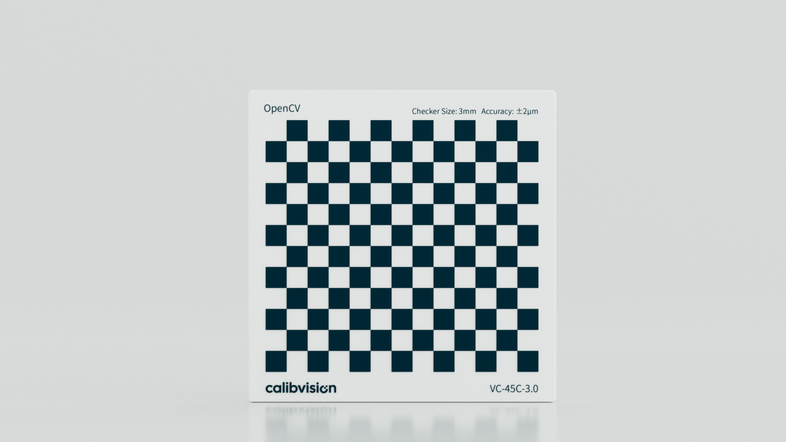
The first is pattern geometry: how many inner corners your checkerboard has. The second is physical square size: how large each square is in the real world, measured in millimeters.
These are separate decisions, and OpenCV treats them separately too. The findChessboardCorners() function — the OpenCV tool that detects your pattern — works with inner corners, not the squares themselves. So a standard 9×6 pattern has 9 inner corner columns and 6 inner corner rows, which means it’s physically a 10×7 grid of squares. If you’re ordering or specifying a calibration target, make sure you and your supplier are speaking the same language.
The pattern geometry decision
Why asymmetry matters
The single most important rule about checkerboard geometry is this: your pattern must be asymmetric. That means the number of inner corners in each direction should be different — 9×6, not 8×8.
Here’s why. A square pattern (like 7×7 inner corners) looks identical when rotated 180°. OpenCV can’t tell the difference, so it produces inconsistent pose estimates between images. That inconsistency feeds directly into a degraded calibration. It’s a subtle mistake, but it’s common, and it costs you accuracy you can’t recover.
A 9×6 pattern is the OpenCV standard for a reason. It’s asymmetric, well-tested, and works reliably across a wide range of camera types. If you need more data points per image — for example, in high-accuracy stereo calibration — an 11×8 pattern is a reasonable step up.
More corners help, up to a point
It might seem like more inner corners always means a better calibration. More data points per image, better statistics, right?
That’s true up to a point. Beyond roughly 10×7, the gains start to diminish. More corners also means smaller squares for a given board size, and smaller squares are harder for findChessboardCorners() to detect cleanly, especially on lower-resolution sensors. The algorithm needs contrast and geometric clarity to work with. Shrink the squares too much and you’re working against it.
For most applications, 9×6 or 10×7 inner corners gives you the right balance.
The physical square size decision
This is where most guides give you a number without explaining why it’s the right number. The reality is that the correct square size depends entirely on your setup.
Match your field of view
The goal is to have your checkerboard cover roughly 25–40% of your camera’s field of view in each calibration image. Too small, and you’re only using a fraction of your sensor — the calibration won’t fully characterize the lens. Too large, and you can’t meaningfully move the board to different positions within the frame, which reduces pose diversity and weakens the calibration.
Start from your working distance and calculate backwards from there.
The pixel rule
There’s a useful rule of thumb here: at your working distance, each square should be at least 20–30 pixels wide in the image. Below that, cornerSubPix() — the OpenCV function that refines corners to sub-pixel accuracy — starts to struggle. You lose the fine localization precision that good calibration depends on.
If your squares come out smaller than 20 pixels in your image, you have two options: increase the physical square size on your target, or move the camera closer for calibration.
For close-range industrial inspection (100–300 mm working distance), squares in the 3–10 mm range usually work well. For mid-range machine vision setups (300–800 mm), something between 10–25 mm is more typical. At longer distances — robotics, automotive, large-format systems — you may need 30 mm or larger.
How many images you need
Once you’ve settled on pattern and square size, the next variable is how many images you feed into the calibration.
OpenCV needs variety more than volume. Ten images from slightly different angles aren’t as useful as ten images from genuinely diverse poses — different positions in the frame (left, center, right, top, bottom), tilted at ±20–30° in both axes, and captured at a range of distances from your working position. Frontal-only captures are a common mistake that results in poor characterization of radial distortion.
For most applications, 20–30 well-distributed images will give you a stable result. For high-accuracy work — stereo vision, structured light, telecentric systems — 40–50 images from carefully distributed poses might be worth the extra effort.
Why your physical target affects the result more than your pattern choice
Here’s something that most OpenCV calibration guides don’t address at all: your corner detection accuracy is bounded by the physical quality of your target.
OpenCV’s cornerSubPix() is mathematically capable of sub-pixel precision. But that precision only materializes if your checkerboard is actually accurate to begin with.
A laser-printed checkerboard on paper can carry positional errors of ±50–200 µm from printer distortion, paper stretch, and humidity-induced warping. That error propagates directly into your calibration results. You might find your reprojection error — the measure of how well your calibrated model predicts corner positions — plateaus above 0.5 pixels no matter how many images you capture. The bottleneck isn’t your algorithm. It’s your target.
Flatness is the other critical factor. If your board bends or curls even slightly, OpenCV interprets that physical warp as lens distortion. You end up “calibrating out” an artifact of your target rather than a property of your lens. The calibration looks complete, but it’s wrong.
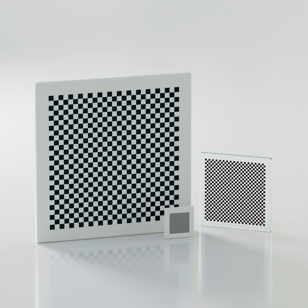
For applications where sub-pixel accuracy actually matters — stereo camera systems, 3D inspection, telecentric lens calibration — a chrome-on-glass checkerboard eliminates these sources of error. The pattern is photolithographically etched onto a quartz glass substrate, accurate to ±0.5 µm, and dimensionally stable across temperature variations. You’re not introducing target error into your calibration; you’re starting from a known, certified baseline.
If you’re working in an environment where a printed target is genuinely good enough, that’s a perfectly reasonable choice. But it’s worth knowing where the ceiling is before you spend time debugging a calibration that can’t get better.
The short version
If you need a quick reference:
Use an asymmetric pattern — 9×6 or 10×7 inner corners works well for most setups. Make sure each square is at least 20–30 pixels wide in your image at your working distance. Capture 20–30 images from varied positions and angles, not just frontal shots. And if your application demands sub-pixel accuracy, your printed target may be the limiting factor — not your code.
If you’re evaluating glass calibration targets for OpenCV use and want to know what specs to look for, our checkerboard calibration plates ship with traceable certificates so you know exactly what accuracy you’re working with before your calibration even starts.
Have a question about choosing the right calibration target for your specific setup? Feel free to reach out — we’re happy to help you think through the specs.