
What is Calibration Pattern?
Calibration patterns serve as the bridge between the physical world and digital camera measurements. These precisely manufactured targets provide known reference points that enable calibration algorithms to calculate camera parameters with high accuracy. Selecting the right pattern directly impacts calibration quality, affecting everything from distortion correction to 3D reconstruction precision.
Types of Calibration Patterns
1. Checkerboard Patterns (Chessboard)
Checkerboard patterns are the most widely used calibration targets, consisting of alternating black and white squares arranged in a grid structure. The calibration algorithm detects corner points (saddle points) where four squares meet.
Key Characteristics:
- Detection Method: Corner detection at square intersections
- Accuracy: High subpixel accuracy possible through corner refinement
- Feature Density: Typically 6×9 or 7×10 grids (48-63 corner points)
- Requirements: For rotation invariance, one dimension must be even and the other odd to avoid 180-degree ambiguity
Advantages:
- Simple to print and manufacture
- Robust corner detection algorithms in OpenCV and MATLAB
- Corner points remain accurate under lens distortion and perspective transformation
- Industry-standard support across all calibration software
Limitations:
- Requires full pattern visibility in most OpenCV implementations
- Difficult to capture edge/corner regions of camera sensor
- Sensitive to lighting conditions causing binarization failures
- Cannot handle partial occlusions
Best Use Cases:
- Single camera calibration in controlled environments
- General-purpose computer vision applications
- Educational purposes and prototyping
- When high-quality, affordable patterns are needed
Technical Specifications:
Recommended Dimensions:
| Square size | Grid size | Border | Printing |
| 20-40mm (based on camera distance) | 7×10 or 9×6 (even×odd configuration) | Minimum 2 square widths of white space | High-quality laser printer or professional printing |
2. ChArUco Boards (Chessboard + ArUco)
ChArUco boards combine checkerboard patterns with ArUco fiducial markers, placing unique binary codes inside white squares of the checkerboard. This hybrid approach leverages both precise corner detection and marker identification.
Key Characteristics:
- Detection Method: ArUco marker detection + corner interpolation
- Accuracy: Higher than pure ArUco, approaching checkerboard precision
- Feature Density: Lower than checkerboards (markers occupy space)
- Unique Feature: Each marker has a unique ID, enabling absolute referencing even with partial board visibility
Advantages:
- Handles partial occlusions gracefully – only visible markers needed
- Enables calibration from extreme image edges, improving distortion parameter estimation
- Robust to non-uniform lighting conditions
- Supports multi-camera network calibration with non-overlapping ID ranges
- Allows occlusions and partial views during calibration
Limitations:
- Requires larger physical size (markers need sufficient resolution)
- Fewer corner points per unit area compared to checkerboards
- More complex detection algorithm
- Requires OpenCV 3.x or later, or specialized libraries
Best Use Cases:
- Hand-eye calibration where robot arms may occlude the pattern
- Multi-camera system calibration
- Wide-angle and fisheye lens calibration
- Industrial applications requiring robustness
- Situations with challenging lighting or partial visibility
Technical Specifications:
Recommended Dimensions:
| Square size | 30-50mm |
| Marker size | 50% of square size (15-25mm) |
| Grid size | 5×7 or 6×8 |
| ArUco Dictionary | DICT_5X5_100 or DICT_6X6_250 |
| Minimum images | 15-20 views for accurate calibration |
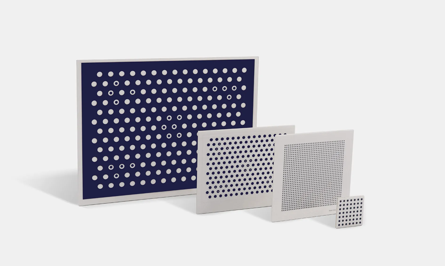
3. Circle Grid Patterns
Circle grid patterns use evenly spaced circles, either white circles on dark background or dark circles on white background, detected as blob features. They come in symmetric and asymmetric configurations.
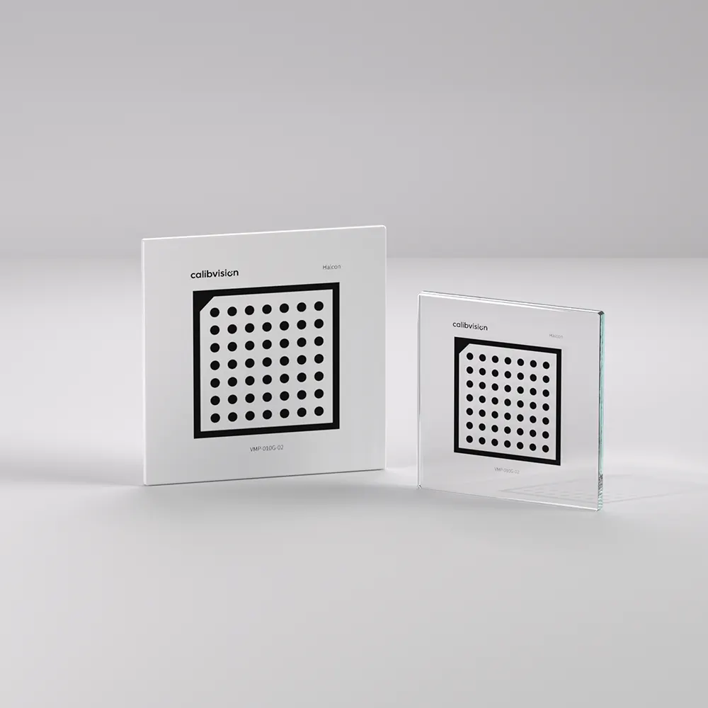
Halcon Compatible Series VMP-010G-02
- Substrate Material: Soda Lime Glass
- Overall Size: 10 x 10mm
- Active Pattern Area: 2.0 x 2.0mm
- Dot Diameter: ø0.25mm
- Dot Spacing: 0.5mm
Symmetric vs. Asymmetric:
- Symmetric Circle Grids: Circles aligned in rectangular grid
- Have 180-degree rotation ambiguity, problematic for stereo calibration
- Use case: Single camera applications only
- Asymmetric Circle Grids: Circles offset in alternating rows
- Unique orientation detection
- Preferred for stereo and multi-camera setups
Key Characteristics:
- Detection Method: Blob detection with circularity, area, and convexity filtering
- Accuracy: Very high precision as all pixels on circle periphery contribute to detection
- Perspective Effects: Circles appear as ellipses under perspective projection, requiring correction
Advantages:
- Reduced noise compared to checkerboards, fewer false corner detections
- Excellent for thermal camera calibration
- Lower sensitivity to image noise due to using entire circle boundary
- Smoother feature extraction process
Limitations:
- OpenCV’s basic detector doesn’t correct for perspective bias – circle centers ≠ ellipse centers
- Requires specialized software (like Calib Camera Calibrator) for highest accuracy
- More difficult to print accurately than checkerboards
- Requires accounting for elliptical shape and projected circle center for high-accuracy calibration
Best Use Cases:
- Thermal and infrared camera calibration
- Applications requiring extreme precision
- When using advanced calibration software (MATLAB, Calib.io)
- Short focal length lenses with significant perspective distortion
Technical Specifications:
Recommended Dimensions:
| Circle diameter | 15-25mm |
| Circle spacing | 1.5× diameter (asymmetric), 2× diameter (symmetric) |
| Grid size | 4×11 (asymmetric) or 7×7 (symmetric) |
| Print quality | Professional printing essential |
4. AprilGrid Patterns
AprilGrid patterns consist of AprilTag fiducial markers organized in grid structure, with each tag contributing four keypoints for calibration.
Key Characteristics:
- Feature Density: Highest space efficiency – 4 corners per marker
- Robustness: Unique tag identification provides additional reference points, enhancing accuracy when markers are occluded or outside field of view
- Applications: Typically used for multi-sensor calibration in UAVs and mobile robots
Advantages:
- Maximum information density per unit area
- Excellent for small calibration targets
- Robust to partial visibility
- Ideal for real-time applications
Best Use Cases:
- UAV and drone vision systems
- Mobile robotics
- Multi-sensor calibration (camera-LiDAR, camera-IMU)
- Space-constrained applications
Pattern Selection Guide
| Pattern Type | Accuracy | Robustness | Edge Coverage | Best Application |
|---|---|---|---|---|
| Checkerboard | ⭐⭐⭐⭐⭐ | ⭐⭐⭐ | ⭐⭐ | General-purpose, controlled environment |
| ChArUco | ⭐⭐⭐⭐ | ⭐⭐⭐⭐⭐ | ⭐⭐⭐⭐⭐ | Industrial, multi-camera, partial occlusion |
| Circle Grid (Asym) | ⭐⭐⭐⭐⭐ | ⭐⭐⭐⭐ | ⭐⭐⭐ | Thermal cameras, high-precision |
| AprilGrid | ⭐⭐⭐⭐ | ⭐⭐⭐⭐⭐ | ⭐⭐⭐⭐ | Robotics, UAVs, space-constrained |
Pattern Quality Requirements
Physical Requirements:
- Flatness: Pattern must be as flat as possible for improved calibration accuracy
- Surface: Matte finish preferred over glossy – reflections degrade detection significantly
- Contrast: Sharp black-white transitions without gradients
- Borders: Most algorithms expect white (or black) border around markers
Manufacturing Options:
- Printed Patterns: Suitable for prototyping and testing (<0.5mm accuracy)
- Professional Printing: High-quality results for most applications (0.1-0.3mm tolerance)
- Metal/Glass Targets: Metrology-grade targets made from glass, carbon fiber, ceramic, or aluminum for highest precision
Mounting Recommendations:
- Rigid backing (foam board, acrylic, or aluminum)
- For large patterns (>30cm), mount vertically or on rigid horizontal support
- Avoid any bowing or warping
- Consider moving camera instead of pattern for large targets
Pattern Size Considerations
Element size should be chosen based on distance and pixel size – larger elements in frame pixels reduce detection uncertainty.
Size Calculation Formula:
Minimum feature size (pixels) = 8-12 pixels
Pattern distance from camera = 0.5 to 3× camera field of view
Optimal coverage = 60-80% of image frame
Practical Guidelines:
- Small patterns (A4 size): Desktop applications, macro lenses
- Medium patterns (60×80cm): Standard camera calibration (1-3m distance)
- Large patterns (1×2m): Wide-angle lenses, large working volumes
- Make squares at least 8×8cm for accurate detection, use 9×6 or 7×8 grid dimensions
Free Pattern Generators
Generate accurate, printable PDF patterns for OpenCV, MATLAB, and photogrammetry software packages:
- calib.io Pattern Generator – ChArUco, checkerboard, circle grids
- OpenCV generate_pattern.py – All pattern types with custom parameters
- MATLAB Camera Calibrator – Built-in pattern generation tools
Summary
Calibration pattern selection significantly impacts final calibration quality. For general applications, start with checkerboards. When working with partial occlusions or edge calibration requirements, ChArUco boards provide superior results. Circle grids excel in thermal imaging and high-precision scenarios. Consider your specific application requirements, available software tools, and environmental conditions when making your selection.