| Property | Positive Pattern | Negative Pattern |
|---|---|---|

|

|
|
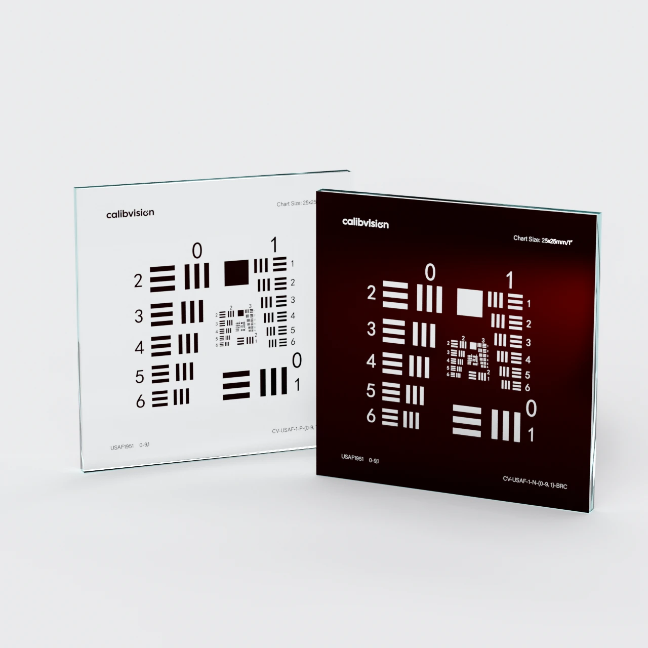
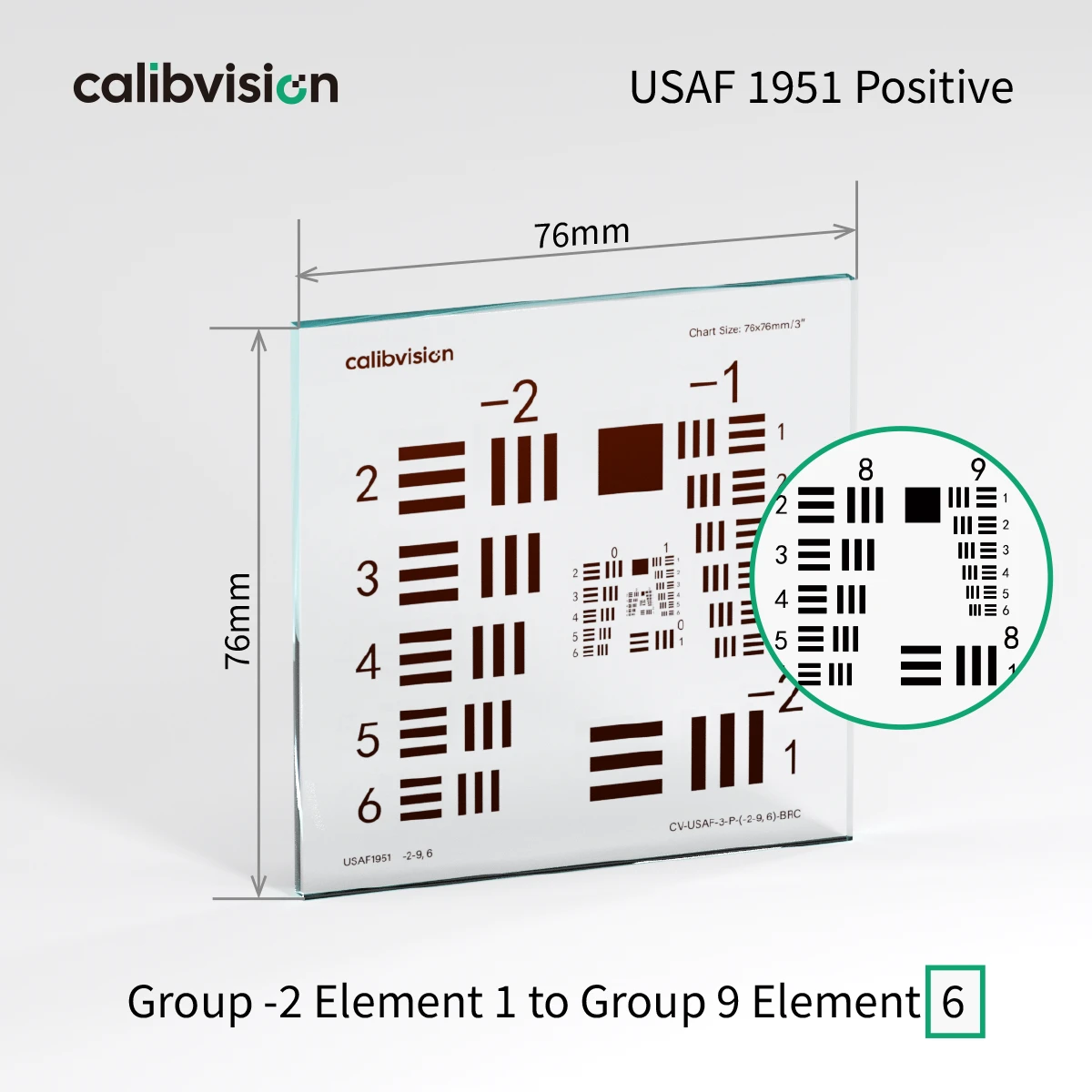
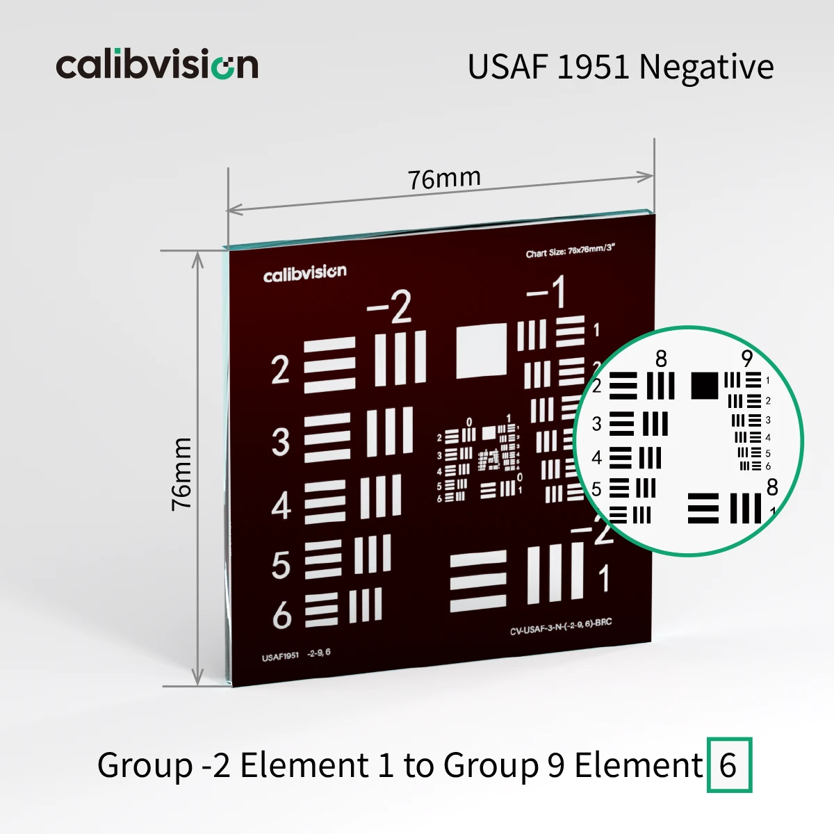
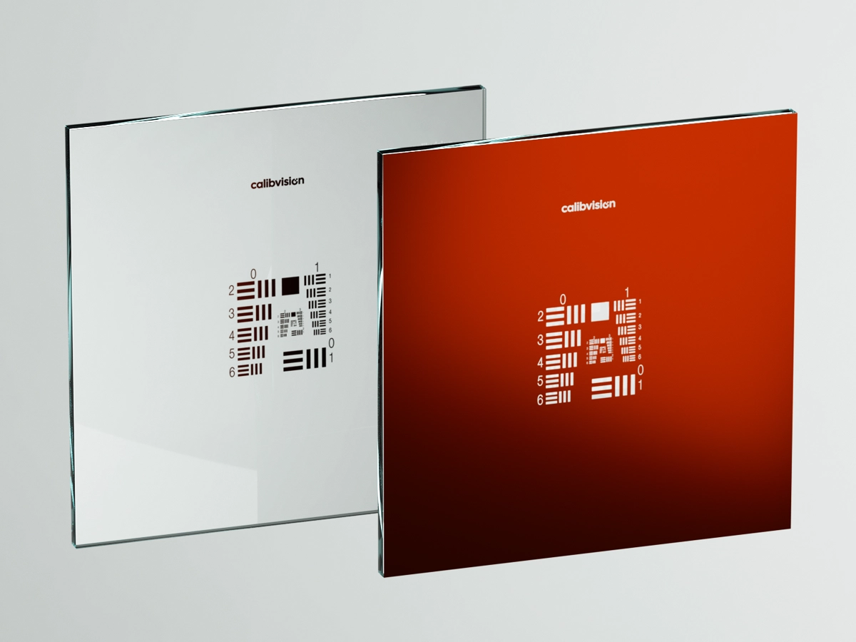
| Pattern (dark) | Chrome (opaque) | Clear (substrate) |
| Background (light) | Clear (substrate) | Chrome (opaque) |
| Best For | Transmission mode with bright field illumination | Transmission mode with dark field illumination |
| Microscope Use | Standard brightfield microscopy | Phase contrast / DIC microscopy |
| Camera Lens MTF | Most common choice | Specialty applications |
| Reflective Setup | Pattern appears dark on bright ceramic | Pattern appears bright on dark chrome |
| Property | Blue Chrome (BLC) | Brown Chrome (BRC) |
|---|---|---|

|

|
|
| Coating Color | Dark blue-gray | Dark brown |
| Background (light) | Clear (substrate) | Chrome (opaque) |
| Best For | Transmission mode with bright field illumination | Transmission mode with dark field illumination |
| Microscope Use | Standard brightfield microscopy | Phase contrast / DIC microscopy |
| Camera Lens MTF | Most common choice | Specialty applications |
| Reflective Setup | Pattern appears dark on bright ceramic | Pattern appears bright on dark chrome |