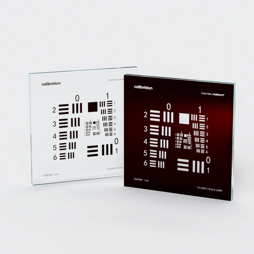
Magnification makes a specimen appear larger, but it does not guarantee that fine details remain distinguishable. A USAF 1951 resolution target provides patterns with known dimensions, helping users evaluate microscope imaging performance during equipment acceptance, configuration comparisons, and routine maintenance.
How the Test Works
The USAF 1951 target contains sets of three horizontal and three vertical bars, identified by group and element numbers. Vertical bars evaluate horizontal resolving capability, while horizontal bars evaluate vertical resolving capability.
During testing, progressively finer elements are examined to identify the highest spatial frequency at which individual bars and their intervening spaces remain distinguishable. Results are expressed in line pairs per millimeter (lp/mm).
Converting Resolution into Micrometer Dimensions
For patterns with equal bar and space widths, individual bar width is calculated as:
[
w=\frac{1000}{2f}
]
where (w) is bar width in micrometers and (f) is spatial frequency in lp/mm. This conversion relates the frequency reading to a physical feature size in the specimen plane.
For example, Group 7, Element 6 corresponds to approximately 228 lp/mm, or a bar width of 2.19 µm. Group 8, Element 1 corresponds to 256 lp/mm, or approximately 1.95 µm.
If the first element is resolved but the second is not, a suitable report would state: “The system resolved the 228 lp/mm element under the specified test conditions and acceptance criterion.” This does not establish the smallest resolvable feature for every specimen type.
Suggested Microscope Testing Procedure
The following procedure provides a starting point for an internal test method:
- Position the target. Place the pattern at the specimen plane. Confirm compatibility with the objective’s working distance and imaging configuration.
- Define the test conditions. Record objective magnification, numerical aperture, illumination, camera settings, and image processing parameters.
- Focus and capture images. Locate a coarse element first, then examine finer elements. Retain the original images.
- Record both orientations. Document horizontal and vertical resolving capability separately.
- Evaluate multiple field positions. Include the center, edges, and corners relevant to the application.
Practical Applications
Equipment Acceptance and Configuration Comparisons
A repeatable target test can help compare performance before and after changing an objective, camera, or intermediate optical component. System resolution depends on optics, illumination, and sensor characteristics, so magnification or pixel count alone cannot establish imaging performance.
Field-of-View Consistency Checks
Sharp central detail does not guarantee equivalent performance at the edges. To assess imaging across a flat specimen plane, maintain a single focus setting while moving the pattern to different field positions.
If each position is refocused independently, report those measurements separately as local best-focus results.
Maintenance Verification
Baseline images captured under a documented configuration can support checks after cleaning, transport, or servicing. Changes can then be investigated alongside illumination, focus, and alignment conditions.
Selecting a Target for the Imaging Mode
Target selection should consider illumination wavelength, transmission or reflection operation, pattern polarity, substrate thickness, and the required frequency range.
Fluorescence microscopy requires a target that produces suitable contrast under the system’s excitation and emission conditions. Dedicated fused silica and fluorescent USAF 1951 targets are available for UV and fluorescence microscopy applications; compatibility should be checked for the intended configuration.
Making Results Repeatable
USAF 1951 targets support rapid resolution checks, but visual interpretation is subjective. For acceptance testing or long-term monitoring, define a consistent acceptance criterion and support visual assessment with image analysis where appropriate.
A useful test record includes the target identifier, resolved group and element, spatial frequency, field position, system settings, and original images. Together, these records provide a practical basis for future comparisons and maintenance decisions.