How Do Machines See in 3D?
Humans perceive depth effortlessly — our two eyes capture slightly different views of the same scene, and our brain fuses them into a three-dimensional understanding of the world.
Machines don’t have that luxury. A standard 2D camera captures a flat image with no depth information. To measure real-world dimensions, detect surface defects, or navigate autonomously, machines need to reconstruct the third dimension — depth.
Over the decades, four primary methods have emerged for 3D imaging in machine vision:
- Stereo Vision — mimics human binocular perception
- Structured Light — projects known patterns to decode surface geometry
- Time-of-Flight (ToF) — measures the travel time of light
- Laser Triangulation — uses geometric relationships between a laser and a camera
Each method offers a different trade-off between accuracy, speed, range, and cost. Let’s break them down one by one.
Stereo Vision: How Two Cameras See Depth
How Stereo Vision Works
Stereo vision — also called binocular vision — is the closest machine analogy to human depth perception.
Two cameras are mounted at a known, fixed distance apart (the baseline). Both cameras capture images of the same scene simultaneously. Because they view the scene from slightly different angles, the position of any given object point will differ between the left and right images. This positional difference is called disparity.
The principle is straightforward:
- Greater disparity → the object is closer to the cameras
- Smaller disparity → the object is farther away
Using the known baseline distance and the calculated disparity, triangulation yields the 3D coordinates of each matched point.
Key Technical Steps
| Step | Description |
| Camera Calibration | Determine each camera’s intrinsic parameters (focal length, principal point, distortion coefficients) and extrinsic parameters (relative position and orientation between cameras) |
| Rectification | Align the two images so that corresponding points lie on the same horizontal line, simplifying the matching process |
| Feature Matching | Find corresponding points between the left and right images using feature descriptors or block matching |
| Disparity Computation | Calculate the pixel offset for each matched point pair |
| 3D Reconstruction | Convert disparity values to real-world 3D coordinates using the calibration parameters |
Pros and Cons
Advantages:
- Intuitive principle, relatively low hardware cost
- Passive method — no additional light source needed
- Can capture 3D information over large scenes and long distances
Limitations:
- Struggles with textureless surfaces (e.g., white walls, uniform-color objects) where feature matching fails
- High computational complexity; real-time performance can be challenging
- Matching accuracy directly depends on calibration quality — poorly calibrated cameras produce incorrect depth maps
Real-World Applications
- Autonomous driving: Perceiving road geometry, vehicles, and pedestrians in 3D
- Robot navigation: Understanding the 3D environment for path planning and obstacle avoidance
- Large-scale 3D reconstruction: Building digital models of architecture, terrain, and landscapes
Structured Light: Decoding 3D Shape from Projected Patterns
How Structured Light Works
Instead of relying on natural scene features like stereo vision, structured light actively projects a known pattern onto the object’s surface.
Here’s the core idea:
- A projector casts a specific light pattern — stripes, grids, or coded dots — onto the object
- If the surface is flat, the pattern appears undistorted
- If the surface has peaks, valleys, or complex geometry, the pattern deforms accordingly
- A camera captures the deformed pattern from a different angle
- By analyzing how the pattern changed, the system calculates the depth of each surface point
Think of it this way: the projected pattern acts like a “ruler of light” draped over the surface, revealing its 3D shape.
Common Types of Structured Light
| Type | How It Works | Characteristics |
| Fringe Projection | Projects parallel sinusoidal stripes; uses phase-shifting to achieve sub-pixel depth resolution | High accuracy; requires multiple exposures |
| Gray Code | Projects binary-coded stripe patterns in sequence; each surface point gets a unique code | Robust; moderate accuracy |
| Speckle / Random Dot | Projects a pseudo-random dot pattern (like Apple’s Face ID); uses correlation for matching | Single-shot; fast; moderate accuracy |
Pros and Cons
Advantages:
- High measurement accuracy, especially at close range
- Works well on surfaces regardless of color or texture — even dark, featureless objects
- Can capture dense 3D point clouds in a single shot or a few exposures
Limitations:
- Sensitive to ambient light — outdoor use under direct sunlight is problematic
- Measurement range is relatively limited compared to ToF or stereo vision
- Calibration is more complex: requires calibrating both the camera and the projector, plus their geometric relationship
Real-World Applications
- Industrial inspection: Measuring 3D dimensions and shape deviations of machined parts
- High-precision 3D scanning: Capturing detailed 3D models of human bodies, dental molds, cultural artifacts
- 3D face recognition: Apple’s Face ID uses structured light (dot projector + IR camera) for secure facial authentication
- Electronics manufacturing: Inspecting solder joints, connectors, and component placement in 3D
Time-of-Flight (ToF): Measuring Depth at the Speed of Light
How ToF Works
Time-of-Flight is the most conceptually simple method: send light out, measure how long it takes to come back.
A ToF camera emits modulated infrared light pulses toward the scene. The light bounces off objects and returns to the sensor. By measuring the round-trip travel time — or equivalently, the phase shift of the modulated signal — the system calculates the distance to every point in the field of view, producing a complete depth map in a single exposure.
Since light travels at approximately 300,000 km/s, the time differences involved are measured in nanoseconds or picoseconds, requiring extremely fast and sensitive electronics.
Two Types of ToF
| Type | Mechanism | Typical Use |
| Direct ToF (dToF) | Measures actual round-trip time of individual light pulses | LiDAR systems, long-range sensing |
| Indirect ToF (iToF) | Measures phase shift of continuous modulated light | Consumer depth cameras (e.g., iPad LiDAR, Azure Kinect) |
Pros and Cons
Advantages:
- Extremely fast — captures full-frame depth maps at high frame rates, enabling real-time applications
- Large measurement range (meters to tens of meters)
- Compact sensor design; easy to integrate
Limitations:
- Depth accuracy is the lowest among the four methods, typically in the centimeter range
- Accuracy degrades with distance
- Sensitive to ambient infrared light (sunlight) and multipath reflections (light bouncing off multiple surfaces before returning)
Real-World Applications
- AR/VR: Real-time 3D scene understanding for immersive experiences (iPad Pro LiDAR, Meta Quest)
- Logistics & warehousing: Rapid volume measurement of packages and pallets
- Autonomous driving: Medium- to long-range obstacle detection
- Gesture recognition: Capturing hand and body movements in 3D
How Laser Triangulation Works
A laser projects a focused spot or line onto the object’s surface. A camera (or position-sensitive detector) observes the laser from a different angle.
When the object’s surface height changes:
- The laser spot/line shifts position in the camera’s field of view
- The amount of shift is proportional to the height change
Using the known geometric relationship — the triangle formed by the laser source, the surface point, and the camera — the system calculates the precise height of each point.
For line laser (laser profile) sensors, the laser projects an entire line, and the camera captures the line’s deformation across the surface profile. By scanning the object (or moving the sensor), a full 3D surface model is built up line by line.
Pros and Cons
Advantages:
- Highest accuracy among all four methods — micrometer-level (μm) precision is achievable
- Relatively simple optical setup
- Excellent for surface profiling and contour measurement
Limitations:
- Measurement range is typically small (millimeters to a few hundred millimeters)
- Measurement speed depends on scanning rate; acquiring a full 3D model takes time
- Surface reflectivity matters — highly specular (mirror-like) or very dark surfaces can cause issues
- Requires precise calibration of the laser-camera geometry; calibration board accuracy must match the micrometer-level precision requirement
Real-World Applications
- Surface profile measurement: Measuring cross-sections of rubber seals, gaskets, and extruded profiles
- Surface roughness inspection: Detecting micro-level defects on machined metal parts
- Weld seam inspection: Measuring weld bead geometry for quality control
- Online/in-line inspection: Real-time dimensional monitoring on production lines (sheet metal thickness, PCB warpage, etc.)
3D Machine Vision Methods: Side-by-Side Comparison
| Feature | Stereo Vision | Structured Light | Time-of-Flight (ToF) | Laser Triangulation |
| Accuracy | Medium (sub-mm) | High (tens of μm) | Low (cm-level) | Very High (μm-level) |
| Speed | Medium | Medium | Very Fast (real-time) | Slow-Medium (scanning) |
| Range | Large (m to km) | Small-Medium (cm to m) | Medium-Large (m to 10s of m) | Small (mm to cm) |
| Ambient Light Sensitivity | Low | High | Medium | Low-Medium |
| Texture Dependency | High (needs features) | Low | None | None |
| Hardware Cost | Low-Medium | Medium-High | Medium | Medium |
| Calibration Complexity | Medium (2 cameras) | High (camera + projector) | Low-Medium | Medium (laser + camera) |
| Best For | Navigation, large scenes | Industrial inspection, 3D scanning | AR/VR, logistics | Surface profiling, precision metrology |
How to Choose the Right 3D Imaging Method
Choosing the right 3D vision method depends on your specific application requirements. Here’s a decision framework:
Choose Stereo Vision If:
- You need 3D perception over a large area (meters to hundreds of meters)
- The scene has sufficient texture and visual features
- Budget is a constraint and you prefer a passive (no projector) setup
- Use cases: outdoor robotics, autonomous driving, drone mapping
Choose Structured Light If:
- You need high accuracy (tens of micrometers) at close to medium range
- The objects have featureless, uniform, or dark surfaces that stereo vision can’t handle
- You’re working in a controlled lighting environment (factory, lab)
- Use cases: industrial 3D inspection, dental scanning, quality control
Choose ToF If:
- Real-time speed is the top priority
- You need full-frame depth at high frame rates
- Centimeter-level accuracy is sufficient
- Use cases: AR/VR, gesture recognition, people counting, logistics
Choose Laser Triangulation If:
- You need the highest possible accuracy (micrometer level)
- You’re measuring surface profiles, contours, or cross-sections
- Measurement range is small and the object can be scanned line by line
- Use cases: weld inspection, seal profile measurement, surface roughness, in-line gauging
Hybrid Approaches
In practice, many advanced systems combine multiple methods. For example:
- Autonomous vehicles often use stereo cameras + ToF LiDAR for complementary near-field and far-field sensing
- Industrial robots may use structured light for part inspection and stereo vision for bin picking
- Smartphone cameras combine ToF depth sensing with computational photography
Why Calibration Is the Foundation of Every 3D Vision System
Here’s the one thing that all four methods have in common: none of them work without proper calibration.
What Calibration Does for Each Method
| Method | What Needs to Be Calibrated | Why It Matters |
| Stereo Vision | Intrinsic parameters of each camera; extrinsic parameters (relative pose between cameras) | Without accurate calibration, disparity-to-depth conversion produces incorrect 3D coordinates |
| Structured Light | Camera intrinsics; projector intrinsics; camera-projector relative pose | The system must know the exact geometric relationship between projector and camera to decode depth from pattern deformation |
| ToF | Lens distortion correction; depth offset calibration; temperature compensation | Raw ToF measurements contain systematic errors that must be calibrated out |
| Laser Triangulation | Camera intrinsics; laser-camera geometric relationship; laser plane calibration | The triangulation calculation depends on knowing the exact angles and distances in the laser-camera-object triangle |
The Accuracy Chain
Think of 3D vision accuracy as a chain — and calibration is the first link.
Calibration Board Accuracy → Camera Calibration Quality → 3D Reconstruction Accuracy → Measurement Result
If the first link is weak — for example, using a calibration target with poor positional accuracy — every downstream step inherits that error. No amount of algorithm optimization can compensate for a fundamentally flawed calibration.
Rule of thumb: Your calibration target’s accuracy should be 3–5× better than your desired measurement accuracy.
Choosing the Right Calibration Board for Your 3D Vision System
Not all calibration boards are created equal. The type, material, and accuracy class of your calibration target should match your 3D imaging method and precision requirements.
Calibration Board Types
| Pattern Type | Description | Best For |
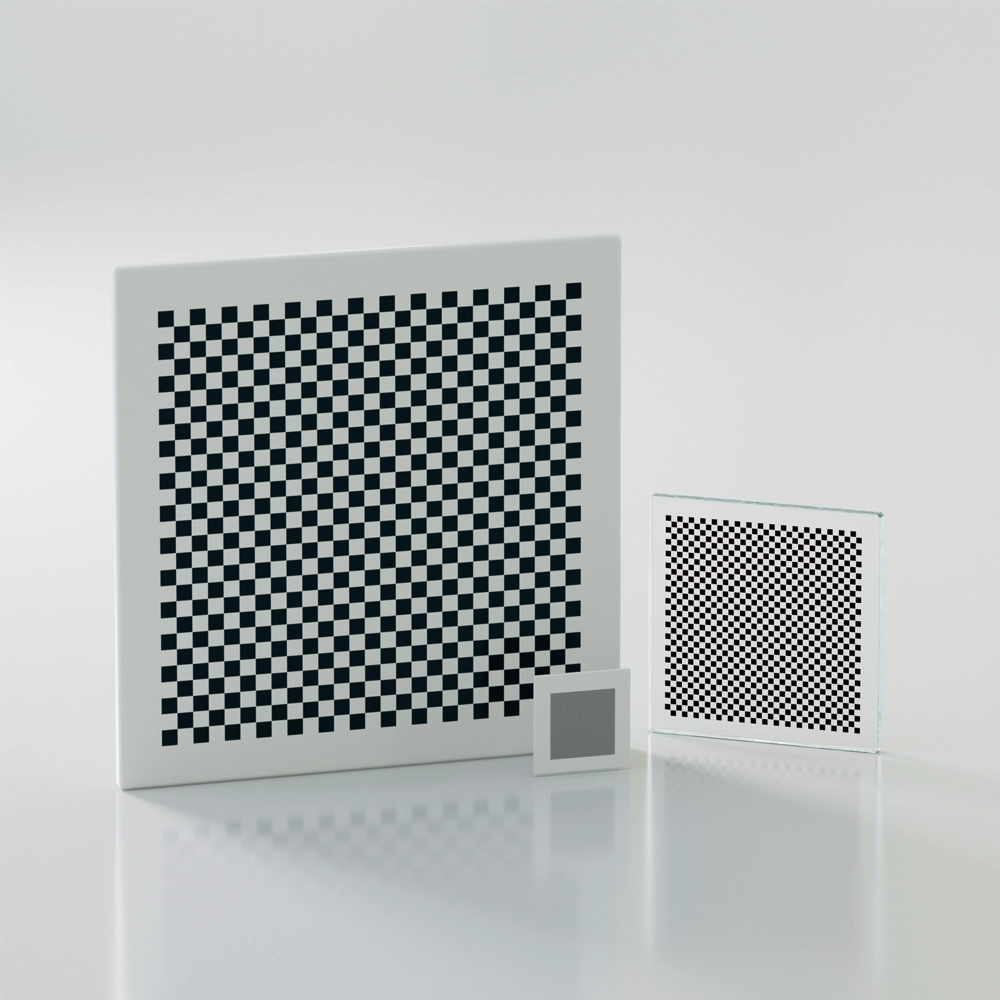
| Checkerboard | Classic black-and-white grid; corner detection is well-supported in OpenCV and Halcon | General-purpose camera calibration, stereo vision |
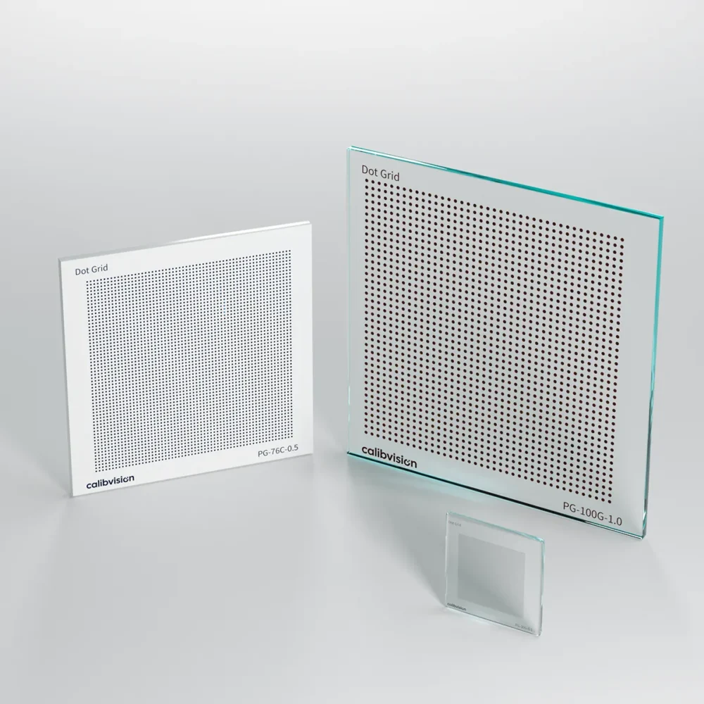
| Circle Grid (Dot Array) | Array of circles; center localization via ellipse fitting provides higher sub-pixel accuracy than corner detection | High-precision calibration, structured light systems |
| ChArUco Board | Hybrid of checkerboard + ArUco markers; works even with partial occlusion | Robotic applications, situations where the board may be partially hidden |
| Cross / Reticle Target | Precision crosshair patterns | Laser triangulation alignment, optical axis calibration |
Calibration Board Materials
| Material | Accuracy | Durability | Best For |
| Chrome-on-Glass (lithographic) | Highest (±5 μm or better) | Fragile; requires careful handling | Laboratory, metrology, laser triangulation |
| Ceramic Substrate | High (±10–20 μm) | Excellent thermal stability, scratch-resistant | Production lines, environments with temperature variation |
| Anodized Aluminum | Moderate (±50–100 μm) | Lightweight, large sizes available, portable | Large-field stereo vision, outdoor calibration, automotive |
| Printed (Paper/Film) | Low (±200+ μm) | Poor; degrades over time | Prototyping, education only |
Matching Calibration Boards to 3D Methods
| 3D Method | Recommended Board Type | Recommended Material | Why |
| Stereo Vision | Checkerboard or Circle Grid | Aluminum or Ceramic | Large field of view often requires bigger boards; needs to be visible from distance |
| Structured Light | Circle Grid or ChArUco | Ceramic or Glass | High accuracy needed; pattern must not interfere with projected light patterns |
| ToF | Flat reference plane / Checkerboard | Aluminum | Used mainly for depth offset calibration; size matters more than micro-precision |
| Laser Triangulation | Circle Grid or Cross Target | Chrome-on-Glass | Micrometer-level accuracy is essential to match the system’s precision |
💡 Pro Tip: Every CalibVision calibration board ships with an individual accuracy inspection report — traceable, verifiable, and unique to your specific board. → View our calibration board catalog
Frequently Asked Questions
What is the most accurate 3D machine vision method?
Laser triangulation offers the highest accuracy, capable of achieving micrometer-level (μm) precision. It is the preferred method for surface profile measurement, precision metrology, and high-accuracy inline inspection. However, its measurement range is typically limited to millimeters or centimeters.
What is the difference between structured light and stereo vision?
Stereo vision is a passive method that relies on natural scene features for depth calculation, while structured light actively projects known patterns onto the object. Structured light achieves higher accuracy and works on featureless surfaces, but is sensitive to ambient light. Stereo vision is better for large-scale, outdoor, or long-range applications.
Do all 3D vision systems require calibration?
Yes. Every 3D machine vision system requires calibration to produce accurate measurements. Calibration establishes the mathematical relationship between pixel coordinates and real-world 3D coordinates. The specific calibration procedure varies by method, but a high-quality calibration board is universally required.
How does calibration board accuracy affect 3D measurement results?
The calibration board’s positional accuracy sets the upper limit of your entire system’s accuracy. A general rule of thumb: your calibration board accuracy should be 3 to 5 times better than your target measurement accuracy. For example, if you need ±50 μm measurement accuracy, your calibration board should have ±10–15 μm positional accuracy or better.
Can I use a printed paper calibration board for 3D vision?
For prototyping and learning, a printed paper target may suffice. For any production or measurement application, printed targets are inadequate — paper warps, ink bleeds, and positional accuracy is typically ±0.2 mm or worse. Industrial-grade glass, ceramic, or aluminum calibration boards are strongly recommended.
What is the best 3D method for industrial inspection?
For close-range, high-precision part inspection, structured light and laser triangulation are the most common choices. Structured light is ideal for capturing full-surface 3D data quickly, while laser triangulation excels at high-resolution profile and contour measurement.
Conclusion: Choose the Method, Then Choose the Calibration
3D machine vision is no longer a niche technology — it’s embedded in everything from smartphone face recognition to autonomous driving to factory quality control.
The four methods we’ve covered each serve different needs:
- Stereo vision for large scenes at moderate accuracy
- Structured light for high-precision close-range inspection
- ToF for real-time depth at moderate accuracy
- Laser triangulation for the ultimate in precision metrology
But regardless of which method you choose, one truth remains constant: your 3D system is only as good as its calibration — and your calibration is only as good as your calibration board.
At CalibVision, we specialize in precision calibration boards and test charts for every 3D vision scenario. From micrometer-accuracy chrome-on-glass targets for laser triangulation to large-format aluminum boards for automotive stereo calibration — every board ships with a traceable accuracy report.
Not sure which calibration board is right for your 3D system? Contact our engineering team → or browse our product catalog →.