A camera finds a calibration target by its printed pattern. A lidar finds the same target by its shape, and sometimes by how strongly each area reflects the laser. Extrinsic calibration needs both sensors to locate the same board in the same place, so a board that works well for a camera on its own can fail once a lidar joins in.
A LiDAR–camera calibration target needs four things: a pattern the camera can detect, a flat and rigid surface the lidar can fit as a plane, edges or holes the lidar can locate, and enough size to hold several lidar scan lines at the working distance.
This guide compares the four target types in common use, shows how to size a board for your lidar, and lists what to specify for material, pattern and mounting.
What Each Sensor Sees on the Target
The two sensors read different things from one board. Table 1 puts them side by side.
| Feature of the target | Camera | LiDAR |
|---|---|---|
| Printed pattern corners | Detected directly, to sub-pixel level | Not seen as geometry; visible only as intensity differences, if the contrast holds at the laser wavelength |
| Board plane | Inferred from the pattern | Measured directly from many points |
| Board edges | Visible, but rarely used | Found where the points stop; limited by point spacing |
| Holes | Seen as outlines | Found as gaps in the point cloud |
| Surface finish | Gloss causes glare that hides the pattern | Gloss sends the return away from the sensor when the board is tilted |
The calibration software then matches the two. That is why the physical relationship between the pattern and the board outline matters as much as the pattern itself.
Four Common Types of LiDAR–Camera Calibration Target
| Target type | How the lidar locates it | Suits | Watch for |
|---|---|---|---|
| Checkerboard on a rigid board | Plane fit plus the four board edges | Most multi-line lidars; MATLAB workflow | Padding between pattern and edge must be known exactly |
| Checkerboard read by intensity | Corners from the reflectance difference between black and white squares | Dense and solid-state lidars | Black and white must differ at the laser wavelength |
| Board with circular holes and markers | Hole centres from gaps in the point cloud | Lower-resolution lidars, down to 16 lines | Needs clear space behind the holes; cut by CNC |
| Plain square board | Edges and corners of the board outline | Simple setups; easy to make | Edge error grows with distance |
Table 2. Four common LiDAR–camera calibration target types.
Checkerboard on a rigid board
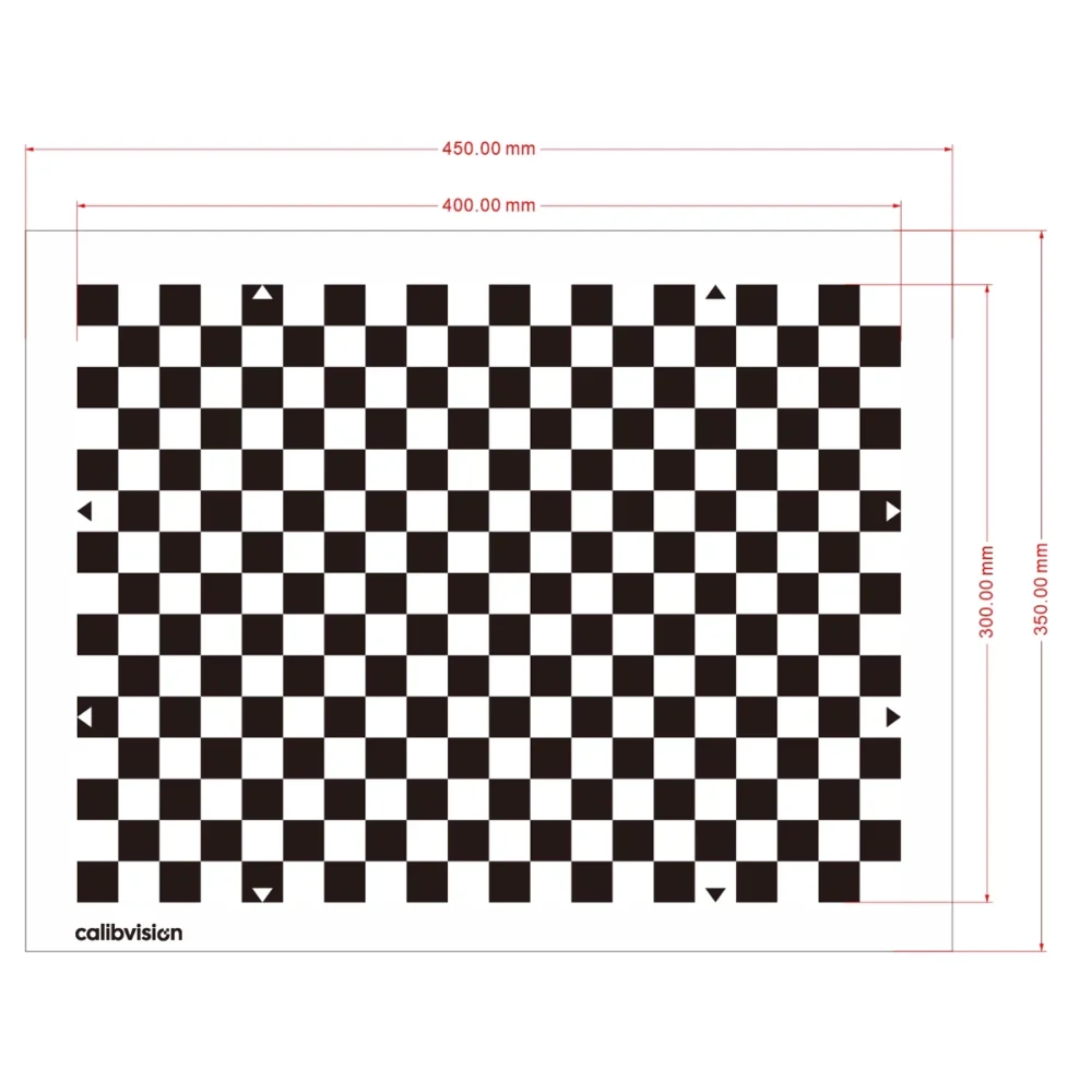
This is the most widely used type. The camera detects the checkerboard corners. The lidar fits a plane to the board and finds its edges. MathWorks’ calibration guidelines ask for a checkerboard with an even number of squares along one side and an odd number along the other, and tell you to measure accurately any padding added around the pattern.
The padding matters because the lidar finds the board by its outline and the camera finds it by its pattern. The offset between the two is the padding. Any error in that number goes straight into the calibration.
Checkerboard read by intensity
Some methods use the lidar’s intensity channel to find the checkerboard corners themselves. ACSC, a method for solid-state lidars, estimates the 3D corners of a printed checkerboard from the reflectance distribution of the points.
This works only if the black and white squares reflect differently at the laser wavelength. An ink that looks black to a camera is not always dark at 905 nm, as we cover in our guide to low-reflectivity LiDAR targets.
Board with circular holes and markers
The Velo2cam method uses a board with four circular holes and four ArUco markers near the corners. The camera reads the markers. The lidar finds the holes as breaks in the point cloud. The authors state that each circle must be represented by at least three points, which for a multi-layer lidar means at least two scan planes crossing each circle. The method is reported to work with lidars of 16 layers.
Plain square board
A square board with no pattern is the easiest target to make. The lidar and the camera both locate its edges and corners. A 2025 study of square targets notes the limit: edge extraction in the point cloud is affected by measurement quantization error, especially at large distances, and a board that is too far or too close gives an incomplete point cluster.
How Large Should a LiDAR–Camera Calibration Target Be?
For the camera, almost any board that fills a fair part of the image will do. The lidar sets the size. What counts is how many scan lines land on the board:
scan lines on the board = board height ÷ (distance × tan(vertical resolution))
| Vertical resolution | 2 m | 5 m | 10 m | 20 m |
|---|---|---|---|---|
| 2.0° (for example 16 lines over 30°) | 14 | 5 | 2 | 1 |
| 1.0° | 28 | 11 | 5 | 2 |
| 0.4° | 71 | 28 | 14 | 7 |
| 0.2° | 143 | 57 | 28 | 14 |
How many lines are enough depends on the method. The Velo2cam authors need at least two scan planes through each hole. For edge-based methods, the geometry gives a floor of four lines, and the reason is the 45° tilt.
Why the board is tilted to 45°
MathWorks recommends tilting the checkerboard to 45° for best results. The geometry explains it. With the board held square, horizontal scan lines run parallel to the top and bottom edges and never locate them. With the board turned onto its corner, every scan line crosses two edges.
Fitting four edge lines takes at least two points on each edge. That means at least four scan lines on the board, two above its widest point and two below. In practice, plan for more than four, because points near an edge are partly on the board and partly on the background. Research on mixed pixels shows that such readings are a weighted average over the beam footprint, so they do not sit exactly on the edge.
Table 3 shows the practical result. A 16-line lidar with 2° resolution keeps four or more lines on a 1 m board only out to about 7 m. MathWorks makes the same point from experience: low-resolution sensors can have trouble accurately detecting distant checkerboards. For a longer working distance, use a larger board, and work through the beam and spacing figures in our guide to LiDAR target size.
Material and Pattern: What Matters for the LiDAR
A camera-only board is judged on pattern accuracy. Add a lidar and five more things count.
- Flatness and rigidity. The lidar fits a plane to the surface, so any bow in the board becomes error in the result. Paper on foam board is fine for a first trial. A station that is used every day needs a substrate that stays flat, such as aluminium honeycomb.
- Known outline dimensions. The distance from the pattern to each edge has to be a known number, not something measured with a tape after printing. Ask for it on the drawing.
- A matte, diffuse surface. Glare hides the pattern from the camera. For the lidar, a diffuse surface still returns light when the board is tilted, where a glossy one reflects the beam away.
- Contrast at the laser wavelength. This matters only for intensity-based methods. If yours is one, ask for the reflectance of the black and white areas at your lidar wavelength, and check it the way you would check any reflectance test report.
- Mounting from behind. MathWorks advises holding the target from behind for sparse lidars, not by its edges, and removing other objects from the plane of the board. Hands, clamps and stands at the edge merge into the board’s outline in the point cloud. Rear mounting points keep the outline clean.
When One Board Is Not Enough: Calibration Walls and Floor Arrays
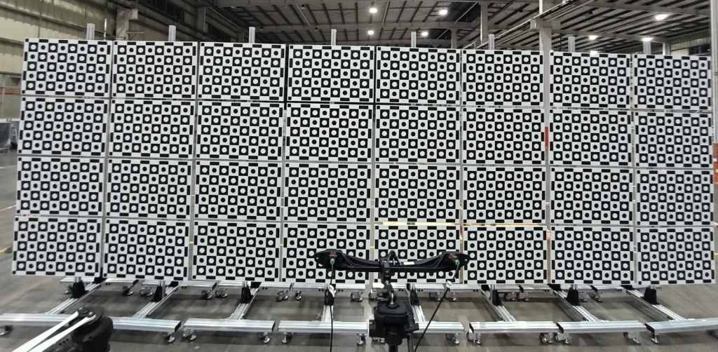
A single board suits one lidar and one camera. A vehicle or robot with many sensors, wide fields of view and long working distances often needs more target area than any one board can give. The usual answer is to tile panels into a wall, and sometimes to add an array on the floor.
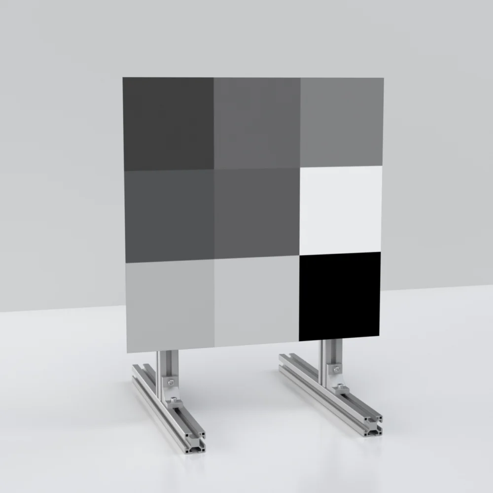
The photos in this article show one such installation built from Calibvision panels: 32 panels in a wall 8 wide by 4 high on wheeled aluminium frames, with a second array laid flat in front of it.
Three things decide whether a wall works as one target:
- The frame holds every panel in a known position, and stays there when it is moved.
- Panel positions are measured after installation, so the software works from real coordinates.
- If the software has to tell panels apart, each panel carries a unique code, as ChArUco boards do.
What to Send When You Ask for a Quote
| What to send | Why it is needed |
|---|---|
| Lidar model, number of lines and vertical resolution | Sets the board size |
| Lidar wavelength | Decides whether pattern contrast must hold in the near infrared |
| Shortest and longest working distance | Sets the board size and the square size |
| Camera resolution and field of view | Sets the square size the camera can resolve |
| Calibration software or method | Decides the pattern type and the even and odd square counts |
| Outer dimensions and padding | The lidar works from the outline |
| Mounting: stand, rear inserts or wall frame | Keeps the edges clear |
| Quantity and layout | One board, or panels for a wall or floor array |
How Calibvision Builds LiDAR–Camera Calibration Targets
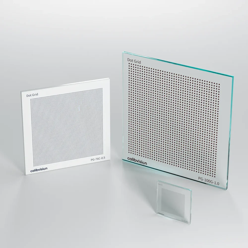
Calibvision makes checkerboard, ChArUco, AprilTag and dot-grid targets on rigid substrates, including 15 mm aluminium honeycomb panels for large formats. Targets are supplied as single boards or as panel sets for walls and floor arrays on aluminium frames, so the total target area is not limited to one board size.
Send us the items in Table 4. We reply with a proposed pattern, board size and mounting, and we confirm pattern contrast at your lidar wavelength if your method needs it.
Frequently Asked Questions
Can I use my camera checkerboard for LiDAR–camera calibration?
Often yes, if it is rigid and flat, its outline dimensions are known, and it is large enough to hold several lidar scan lines at your working distance. A paper print taped to cardboard usually fails on flatness.
Why tilt the calibration board to 45°?
With the board held square, horizontal scan lines never cross the top and bottom edges. Tilted, every scan line crosses two edges, so all four can be located.
How big should the board be for a 16-line LiDAR?
At 2° vertical resolution, a board 1 m tall holds 5 scan lines at 5 m and only 2 at 10 m. Keep the board within about 7 m, or use a larger one.
Does the LiDAR need to see the checkerboard pattern?
Only for intensity-based methods. Plane and edge methods use the board’s geometry, and the pattern serves the camera.
Checkerboard or ChArUco for LiDAR–camera calibration?
Follow what your software supports, since some tools require a plain checkerboard. ChArUco helps when the camera sees only part of the board or has to tell several boards apart.
How many poses should I capture?
MathWorks recommends at least 10 frames. Vary the position and angle of the board across the field of view the two sensors share.
Can several panels be combined into one large target?
Yes. Panels can be tiled into a wall or a floor array on a rigid frame. Measure the panel positions after installation so the software works from real coordinates.