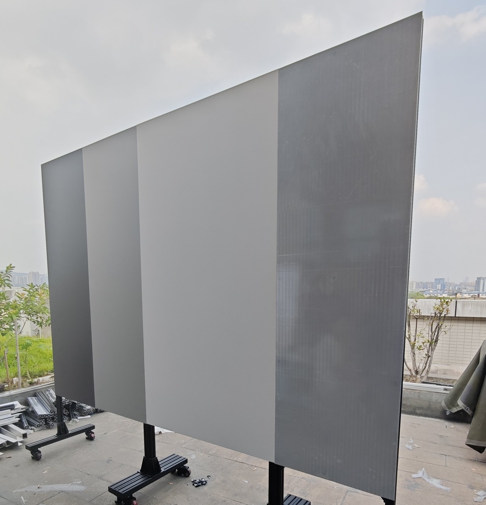
A reflectance target that gives clean data at 20 m can give misleading data at 200 m. The panel is the same. What changed is the beam, which has spread, and the scan points, which have moved apart. Fewer points land on the panel, and some of them only partly.
A LiDAR test target should be at least as wide as the number of points your test needs, multiplied by the point spacing at the test distance, plus one beam spot diameter. Work out width and height separately, because most sensors have different horizontal and vertical resolution.
For a sensor with 0.1° angular resolution and 2 mrad beam divergence, that comes to about 0.7 m for three full points at 100 m, and about 1.5 m at 200 m. The sections below show where those numbers come from, so you can run the same calculation for your own sensor before you order a target.
Two Things Grow with Distance: Beam Spot and Point Spacing
Target size depends on two sensor properties. Both scale linearly with distance.
Beam spot diameter
A lidar beam leaves the sensor a few millimetres wide and then spreads at a fixed angle, its divergence. The spot diameter on the target is the exit diameter plus the distance multiplied by the full divergence angle in radians. Edmund Optics gives the exact form: output diameter = input diameter + 2 × distance × tan(divergence / 2).
As an example, the Ouster OS1 Rev7 datasheet lists a 9.5 mm beam at the sensor and 0.18° (FWHM) divergence. That gives a spot of about 17 cm at 50 m and about 29 cm at 90 m.
| Full-angle divergence | 50 m | 100 m | 150 m | 200 m | 300 m |
|---|---|---|---|---|---|
| 1 mrad (0.057°) | 5 cm | 10 cm | 15 cm | 20 cm | 30 cm |
| 2 mrad (0.115°) | 10 cm | 20 cm | 30 cm | 40 cm | 60 cm |
| 3 mrad (0.172°) | 15 cm | 30 cm | 45 cm | 60 cm | 90 cm |
Check two details on the datasheet before you use its divergence figure:
- How divergence is defined. Some manufacturers quote FWHM, others the 1/e² width. For a Gaussian beam the 1/e² diameter is about 1.7 times the FWHM diameter, so the same beam can carry two quite different numbers. For target sizing, use the wider definition when you have it.
- Whether the beam is round. Many sensors have different divergence horizontally and vertically. Use each value for its own axis.
Point spacing
Point spacing is the gap between neighbouring measurement points on the target. It equals distance × tan(angular resolution). Angular resolutions of 0.1° to 0.2° are the figures usually stated for automotive lidar, according to a requirements study in Sensors. At 0.1°, neighbouring points are 17.5 cm apart at 100 m and 35 cm apart at 200 m.
| Angular resolution | 50 m | 100 m | 150 m | 200 m | 300 m |
|---|---|---|---|---|---|
| 0.05° | 4.4 cm | 8.7 cm | 13.1 cm | 17.5 cm | 26.2 cm |
| 0.1° | 8.7 cm | 17.5 cm | 26.2 cm | 34.9 cm | 52.4 cm |
| 0.2° | 17.5 cm | 34.9 cm | 52.4 cm | 69.8 cm | 104.7 cm |
Why the Target Must Be Larger than the Beam Spot
Reflectivity and range specifications assume the target catches the whole beam. Two things go wrong when it does not.
Partial hits read darker than the panel really is
When the spot is larger than the target, or hangs over its edge, only part of the pulse is reflected. While the target is larger than the spot, the return falls with the square of distance. Once the target is smaller than the spot, it falls with the fourth power, as Allegro MicroSystems shows in its range derivation.
The sensor cannot tell that the panel was only half illuminated. It reports a lower intensity, and a 10% panel can look like a much darker object. Near the range limit the point drops out altogether, and the measured detection range comes out shorter than the sensor can really achieve.
Edge hits mix the panel with the background
A lidar range reading is a weighted average over the whole footprint of the beam. When the footprint straddles the panel edge, part of the pulse returns from whatever is behind the panel, and the reported point can sit between the two surfaces. These are called mixed pixels. A study in Remote Sensing states the requirement plainly: the object has to be large enough that at least one point on its surface is not a mixed pixel.
So the points that count are full points, those whose entire spot lies on the panel. Remove edge points before you compute any statistic.
LiDAR Target Size Rule: Points × Spacing + One Spot Diameter
Size each axis with the same rule:
W ≥ n × s + d
- W is the target width (or height).
- n is the number of full points you need along that axis.
- s is the point spacing at the test distance.
- d is the beam spot diameter at the test distance.
The “+ d” term is the edge margin. A point is a full point only if its centre sits at least half a spot diameter inside each edge, and that takes one spot diameter off the usable width.
The rule uses n × s, not (n − 1) × s, because you cannot control where the scan grid falls on the panel. With a usable width of n × s, at least n points land fully on the panel wherever the grid happens to sit.
| Full points per axis | 50 m | 100 m | 150 m | 200 m | 300 m |
|---|---|---|---|---|---|
| 3 | 0.36 m | 0.72 m | 1.09 m | 1.45 m | 2.17 m |
| 5 | 0.54 m | 1.07 m | 1.61 m | 2.15 m | 3.22 m |
| 10 | 0.97 m | 1.95 m | 2.92 m | 3.89 m | 5.84 m |
Read the other way round, a 1.2 m panel with this example sensor holds three full points out to roughly 165 m, and five full points out to roughly 110 m. If the vertical resolution is 0.2°, the same panel holds three full rows only to about 95 m.
How Many Points Do You Need on the Target?
There is no single standard number. It follows from what the test measures.
- Detection range and probability of detection. The Sensors requirements study assumes a target counts as detected when it shows at least one point in a frame. One full point is the floor, and it leaves no margin for aiming error. We suggest at least three points across, so the middle one stays clear of both edges even if alignment drifts.
- Reflectivity or intensity accuracy. Single-point intensity is noisy. We suggest 5 to 10 full points per axis, so you can average and also see whether the readings are uniform across the panel.
- Range accuracy and precision. These are statistics over many samples. Frames add samples over time, so a few full points can be enough, but every one of them has to be a full point.
Whichever number you choose, record the target size, the distance and the number of points used next to the result. Cepton makes the same point about range claims: they can only be compared fairly when reflectivity, probability of detection and target size are all stated.
Worked Examples from Two Published Datasheets
Example 1: a long-range sensor at 200 m
The Hesai AT128 product page lists 0.1° (H) × 0.2° (V) angular resolution and a 210 m range at 10% reflectivity. At 200 m, points are 35 cm apart horizontally and 70 cm apart vertically.
A 1.22 m square panel catches three point centres across and a single row. A 2.44 m panel catches six across and three rows. The product page does not list beam divergence, so the count of full points will be lower once the spot diameter is subtracted. Ask the manufacturer for that figure before you fix the size.
Example 2: a 360° sensor at 90 m
The Ouster OS1 Rev7 datasheet gives a 90 m range on a 10% target, 0.18° (FWHM) divergence and a 9.5 mm exit beam. In the 2048 × 128 mode, the horizontal step is 360° / 2048 = 0.176°. The 45° vertical field of view across 128 channels gives about 0.35° per channel, assuming even spacing.
At 90 m that is 28 cm × 56 cm point spacing with a 29 cm spot. A 1.22 m panel has 0.93 m of usable width: three full points across and one row. Switch to the 1024 mode and the horizontal spacing doubles to 55 cm, which leaves one full point across.
| Item | Hesai AT128 at 200 m | Ouster OS1 (2048 × 128) at 90 m |
|---|---|---|
| Angular resolution (H × V) | 0.1° × 0.2° | 0.176° × 0.35° |
| Point spacing (H × V) | 35 cm × 70 cm | 28 cm × 56 cm |
| Spot diameter | Not listed on the product page | 29 cm (FWHM) |
| 1.22 m panel | 3 × 1 points (spot not subtracted) | 3 × 1 full points |
| 2.44 m panel | 6 × 3 points (spot not subtracted) | 7 × 3 full points |
Both examples point the same way. At the rated 10% range, a 1.2 m panel gives one row of points. The vertical axis runs out first.
When One Panel Is Not Large Enough
Table 3 asks for panels of 2 m and more at long range. There are four practical ways to get there.
Order a larger or rectangular panel
Size each axis on its own. If the vertical resolution is half as fine as the horizontal, the panel needs to be taller than it is wide, not square.
Tile several panels on one frame
Panels of the same nominal reflectance, mounted edge to edge on a rigid frame, act as one large target. Three conditions apply. The surfaces have to sit in one plane. Points that fall on a seam have to be excluded. And each panel should come with its own measured reflectance value, so that panel-to-panel differences are known, not assumed.
Move accuracy tests closer
Reflectivity accuracy does not have to be measured at maximum range. Run it at a distance where the panel holds 5 to 10 full points per axis. Keep the long-range position for detection checks, where fewer points are acceptable.
Use the densest scan mode
If the sensor offers a higher-resolution mode, the same panel holds more points. Report the mode with the result.
Two setup details protect whatever size you choose. Keep the panel square to the beam: a panel tilted by 30° presents only 87% of its width. And leave clear space behind the panel, so any mixed-pixel points sit well away from the surface and are easy to filter out.
Target Sizing Checklist
Collect these inputs before you ask for a quotation.
| Input | Where to find it | What it decides |
|---|---|---|
| Maximum test distance | Test plan | Every other number scales with it |
| Angular resolution, H and V, in the scan mode used | Sensor datasheet | Point spacing on each axis |
| Beam divergence, H and V, and its definition (FWHM or 1/e²) | Datasheet or manufacturer | Spot diameter and edge margin |
| Exit beam diameter | Datasheet | Adds to the spot diameter |
| Full points needed per axis | Test plan | The multiplier n in the sizing rule |
| Angle of incidence | Test plan | Projected width = W × cos(angle) |
| Mounting and handling | Test site | Inserts, frame, panel weight, crate |
How Calibvision Supplies Large LiDAR Targets
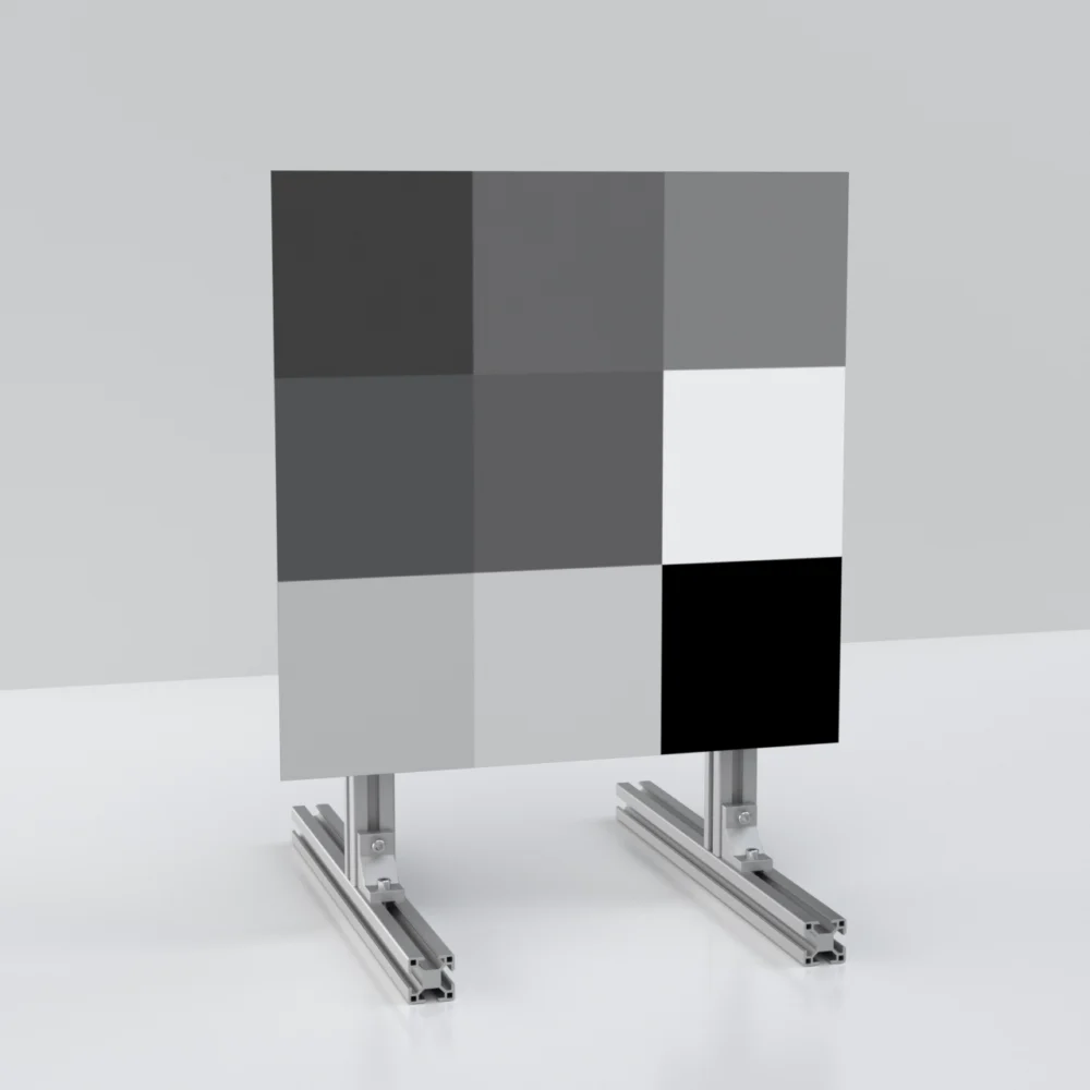
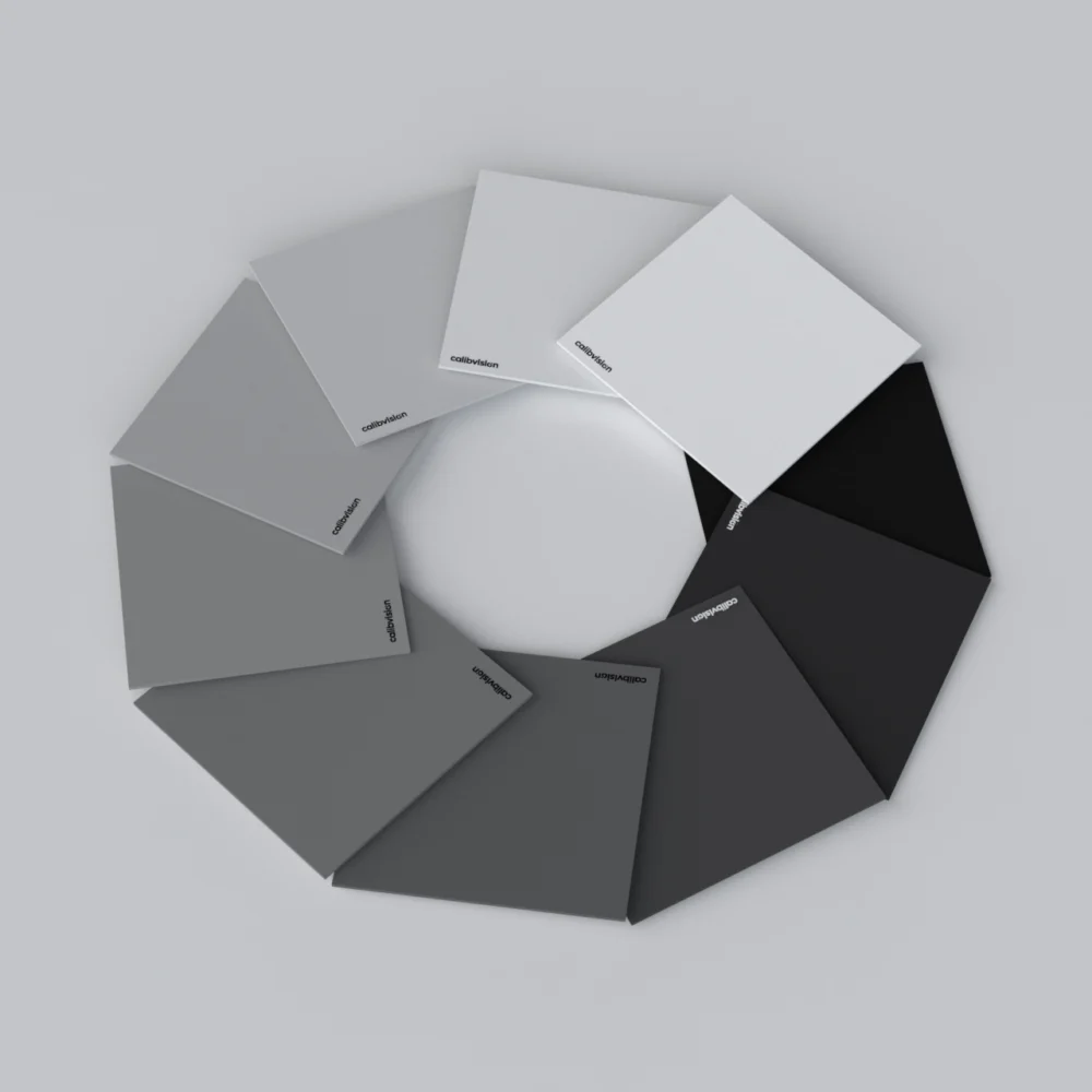
Calibvision builds diffuse reflectance targets for lidar testing on 15 mm aluminium honeycomb panels. A typical large configuration is 1219.2 × 1219.2 mm (4 ft × 4 ft) with threaded inserts on the rear face for frame mounting. Reflectance is specified at 905 nm and 1550 nm, each panel ships with its own measured reflectance report, and panels are packed in a wooden crate.
Other sizes, rectangular formats and matched sets for tiling are made to order. Send us the test distance, the sensor’s angular resolution and its beam divergence, and we will reply with a recommended size and the calculation behind it.
Frequently Asked Questions
How big should a LiDAR target be at 100 m?
For a sensor with 0.1° resolution and 2 mrad divergence, about 0.7 m gives three full points per axis and about 1.1 m gives five. Coarser resolution or a wider beam needs a larger panel, so run the rule with your own sensor’s figures.
Does the target have to be larger than the laser spot?
Yes. If the spot is larger than the panel or hangs over an edge, only part of the pulse is reflected and the reading comes out darker than the panel’s real reflectance. The panel should exceed the spot by enough to hold the number of points your test requires.
How many LiDAR points should land on the target?
One full point is the minimum for a detection check. We suggest three across as a practical minimum, and 5 to 10 per axis when you measure reflectivity accuracy and want to average.
Can I use several smaller panels instead of one large target?
Yes, if the panels have the same nominal reflectance, sit in one plane on a rigid frame, and each has its own measured reflectance value. Exclude the points that fall on the seams.
Why are readings different near the edge of the target?
Edge points are partly on the panel and partly on the background. Their intensity is lower, and their range can fall between the panel and whatever is behind it. Leave them out of the analysis.
Does a LiDAR target need to be square?
No. Horizontal and vertical resolution usually differ, so each axis has its own minimum size. A rectangular panel is often the more efficient choice.
Is a 1.2 m target enough for 200 m testing?
For a detection check, often yes. With 0.1° × 0.2° resolution it holds about three points across but only one row, which is too few for accuracy statistics. For those, use a larger or tiled target, or test at a shorter distance.