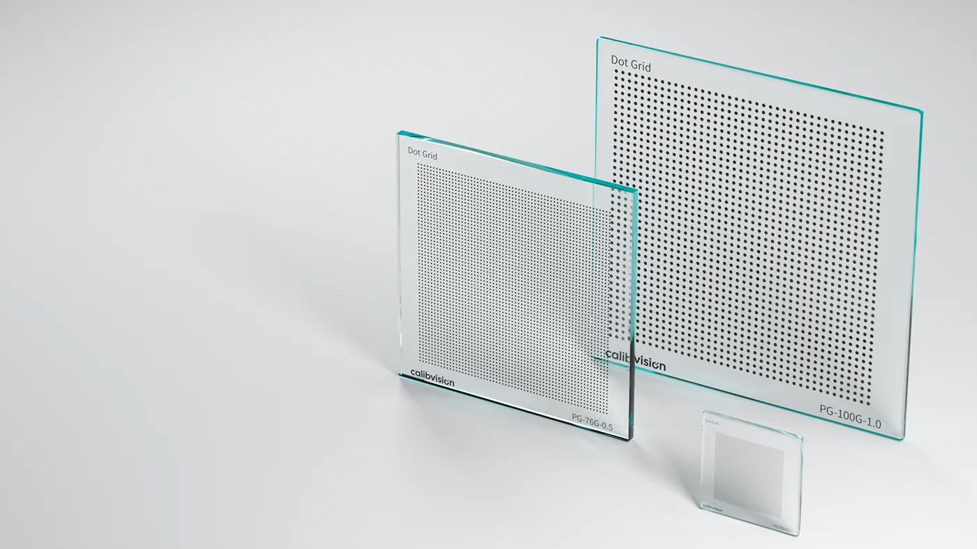
A checkerboard and a dot grid solve the same problem: they give a camera a dense, regular set of reference points with precisely known positions. They differ in one fundamental way — what the detector actually measures. A checkerboard is located by its corners (the saddle points where four squares meet); a dot grid by the centroids of its dots. That single choice drives everything downstream: accuracy under perspective, feature density, software support, and lighting.
The key result, stated up front: a checkerboard corner is projectively invariant — it images to a corner with no systematic offset — while a dot centroid carries a small perspective bias that must be corrected in software. This article explains how corner and centroid detection differ, why that bias arises, which toolchain expects which pattern, and how to choose for your setup.
What is the difference between a checkerboard and a dot grid?
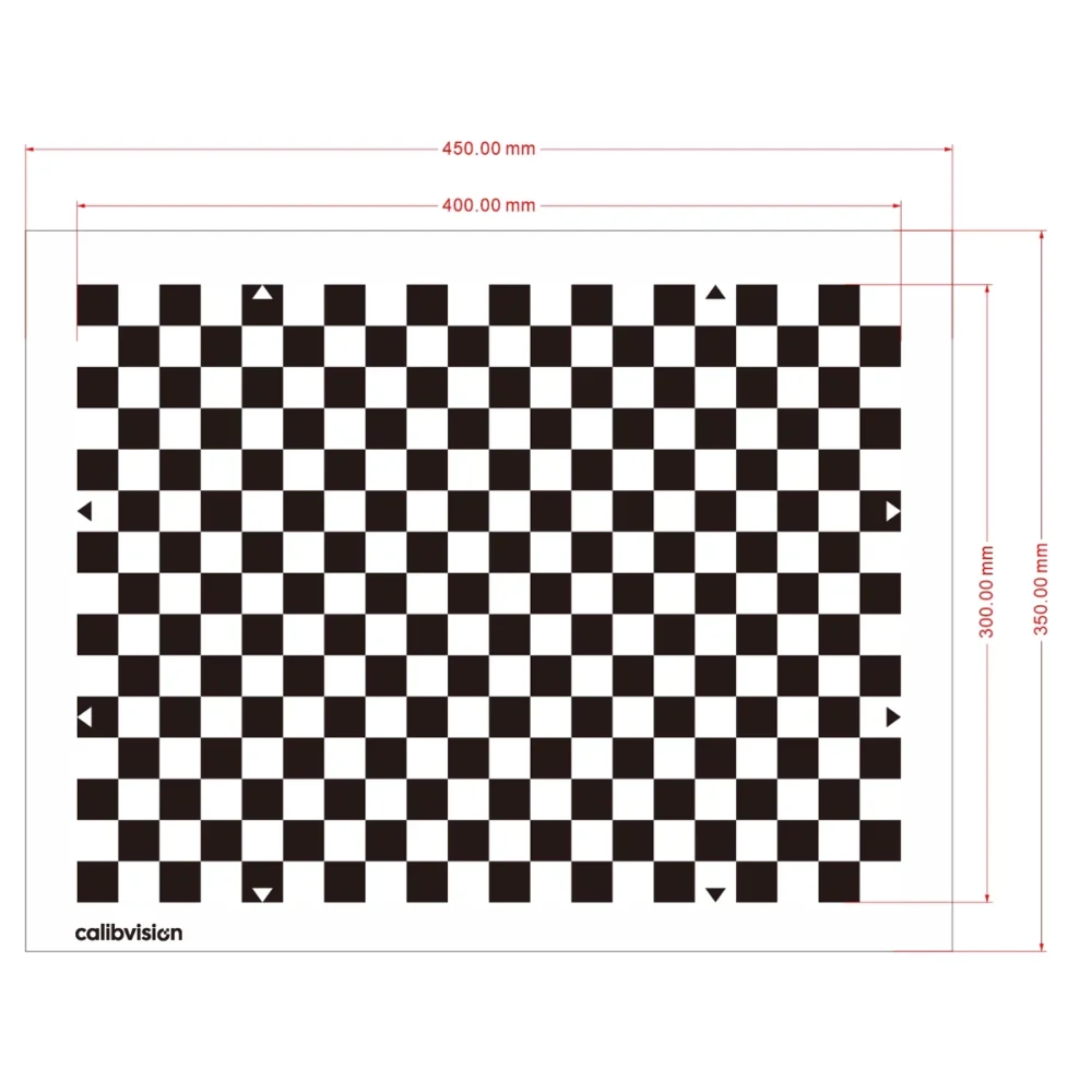
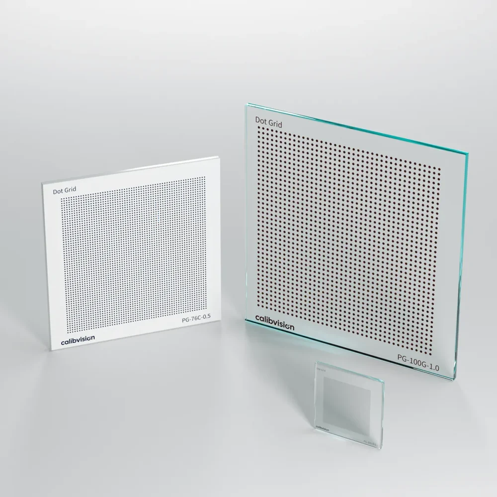
A checkerboard is an array of alternating black and white squares; the algorithm detects the saddle corners between them. A dot grid is a regular array of solid dots (filled circles); the algorithm detects each dot’s centroid. Both produce a dense, regular field of known points. The meaningful difference is the feature type — corner versus centroid — and that difference has real, measurable consequences.
How does corner detection differ from centroid detection?
The two are located in fundamentally different ways, and each has a distinct error signature.
- Corner (saddle point). Located by fitting the intersection of the surrounding edges. Because each corner is bounded by two black squares, the edge gradients are strong and sub-pixel refinement is sharp. A corner is geometrically exact but uses relatively few pixels, so its random noise per point is moderate.
- Centroid. Located by averaging the many pixels that make up a dot. Averaging over a large area drives random noise very low — dot centers can be located to a few hundredths of a pixel. But the centroid is only the true center when the projection of the dot is symmetric.
Why do dot-grid centroids carry a perspective bias?
Under perspective projection, a circle does not image to a circle — it images to an ellipse. And the centroid of that ellipse is not the image of the circle’s true center. There is a small offset, called eccentricity or perspective bias, that grows with viewing obliquity and with dot size; lens distortion adds a further offset. A naive centroid detector bakes this bias straight into the calibration as a systematic error.
A checkerboard corner has no equivalent problem. The intersection of two lines images to the intersection of two lines under any projective transform, so a corner projects exactly to a corner. Lens distortion still bends it — but that is precisely what calibration is solving for, and there is no additional centroid-type offset layered on top.
So which pattern is more accurate?
It is a bias-versus-variance trade-off, and the honest answer is that it depends on the detector:
- Corners are unbiased but slightly noisier per point.
- Centroids are lower-noise but biased unless the detector models the ellipse.
With bias-aware software — Halcon’s CALTAB, or an OpenCV circle-grid pipeline handled correctly — a dot grid corrects the eccentricity and keeps its low noise, so it can match or exceed a checkerboard. With naive centroiding, the bias dominates and a checkerboard wins. “More accurate” is really a question of which detector you are running.
Which software supports each pattern?
Toolchain is usually the deciding factor, because each ecosystem is built around one pattern.
| Toolchain | Native pattern | Notes |
|---|---|---|
| OpenCV | Checkerboard | findChessboardCorners is the default; findCirclesGrid also supports symmetric/asymmetric circle grids |
| MATLAB | Checkerboard | Camera Calibrator app is checkerboard-first |
| HALCON | Dot grid (CALTAB) | Metrology-grade; built-in eccentricity correction |
| ROS / Kalibr | AprilGrid | Separate coded pattern — see our AprilGrid guide |
Checkerboard vs dot grid — side by side
| Checkerboard | Dot grid | |
|---|---|---|
| Feature measured | Saddle corner | Dot centroid |
| Perspective bias | None (projective-invariant) | Present — needs software correction |
| Noise per feature | Moderate | Low |
| Feature density | High | Very high |
| Native ecosystem | OpenCV, MATLAB | HALCON (CALTAB) |
| Best for | Open-source, single/stereo, general MV | Halcon metrology, backlit, dense-feature work |
Which should you choose?
| Your setup | Recommended | Why |
|---|---|---|
| OpenCV / MATLAB, single or stereo camera | Checkerboard | Unbiased corners, best-supported, simplest pipeline |
| HALCON, highest precision | Dot grid (CALTAB) | Low-noise centroids with built-in bias correction |
| Backlit stage / dense feature field | Dot grid | Very high feature density, clean centroids under backlight |
| Board often partly out of frame / multi-camera | Neither — use ChArUco | Coded IDs allow partial views; see our ChArUco guide |
If your board is frequently tilted, occluded, or only partly in frame, both plain patterns struggle, because both need the full grid resolved. That is the specific gap ChArUco boards fill by adding a coded ID to every corner.
Why the target — not the algorithm — sets your accuracy ceiling
Whichever pattern you choose, the calibration cannot be more accurate than the board it is derived from. A laser-printed paper target carries ±50–200 µm of positional error and warps, and that error propagates straight into your result no matter how good your camera or code is. A photolithographic chrome pattern on a flat, dimensionally stable substrate removes that error source:
| Substrate | Feature accuracy | Best for |
|---|---|---|
| Quartz glass (blue chrome) | ±0.5 µm | Metrology, thermal/UV, microscopy |
| Soda-lime glass (brown chrome) | ±1 µm | Backlit precision machine vision |
| Matte ceramic (blue chrome) | ±2 µm | Front-lit, rugged production floors |
Both our ChessMark checkerboards and dot grids share these tiers, and every target ships with a serial-numbered inspection report; NIST/NIM-traceable, CNAS-accredited (ILAC-MRA-recognised) third-party calibration is available on request. For what a trustworthy inspection report must contain, see how we measure and report target accuracy.
Which models are in stock?
Both lines are standard, in-stock, and read directly from the model number.
ChessMark checkerboards — CM-[substrate]-[checker mm]-[chrome]. Sizes 25–127 mm, checkers 0.1–4.0 mm.
| Model | Substrate | Overall size | Checker | Accuracy |
|---|---|---|---|---|
| CM-100SG-2.0-BRC | Soda-lime · brown | 100×100 mm | 2.0 mm | ±1 µm |
| CM-100QG-2.0-BLC | Quartz · blue | 100×100 mm | 2.0 mm | ±0.5 µm |
| CM-100C-2.0-BLC | Matte ceramic · blue | 100×100 mm | 2.0 mm | ±2 µm |
| CM-25QG-0.1-BLC | Quartz · blue | 25×25 mm | 0.1 mm | ±0.5 µm |
Dot grids — PG-[substrate]-[dot mm]-[chrome]. Sizes 15–250 mm, dots 0.1–2.0 mm, Halcon-ready.
| Model | Substrate | Overall size | Dot | Accuracy |
|---|---|---|---|---|
| PG-100SG-1.0-BRC | Soda-lime · brown | 100×100 mm | 1.0 mm | ±1 µm |
| PG-100QG-1.0-BLC | Quartz · blue | 100×100 mm | 1.0 mm | ±0.5 µm |
| PG-100C-1.0-BLC | Matte ceramic · blue | 100×100 mm | 1.0 mm | ±2 µm |
| PG-250QG-2.0-BLC | Quartz · blue | 250×250 mm | 2.0 mm | ±0.5 µm |
Full lists, pricing and configurators: ChessMark checkerboard targets and dot grid targets.
How do I order the right target?
Send your software (OpenCV, MATLAB, HALCON), substrate, overall size, feature size, and working distance — or just describe the application and our engineers will spec the pattern, size and substrate for you. Standard targets ship in 4–6 working days with a dimensional inspection report.