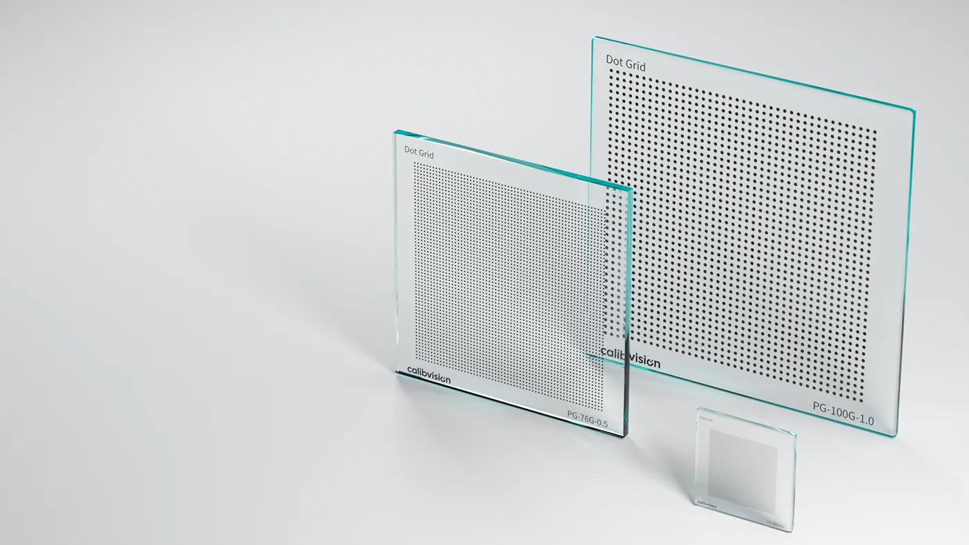
A circle grid is the third common OpenCV calibration pattern, after the checkerboard and ChArUco. It comes in two layouts — symmetric and asymmetric — and the choice is not cosmetic: it changes whether the pattern can be oriented unambiguously, how many points it carries, and how you count patternSize in findCirclesGrid. This guide covers both layouts, why the asymmetric grid is the recommended default, the counting gotcha that trips people up, and the centroid-bias caveat that applies to any circle-based target.
What is a circle grid?
Instead of the intersecting edges of a checkerboard, a circle grid presents a field of filled circles, and the feature the software locates is each circle’s centroid. In OpenCV, findCirclesGrid detects the circles with a blob detector and returns their centres. Because a centroid is averaged over many pixels, it can be very low-noise — but it also carries a systematic bias under perspective, which we come back to below. For the corner-versus-centroid trade-off in full, see checkerboard vs dot grid.
The symmetric circle grid
A symmetric grid is a regular rectangular array — circles evenly spaced in straight rows and columns. Its patternSize is simply the number of circles across and down, e.g. a 9×6 grid.
The problem is that a regular rectangular array is rotationally symmetric: rotate it 180° and it looks identical. The calibration can then assign the origin to the wrong corner and flip the coordinate frame, exactly the ambiguity that catches people out with even-by-even checkerboards. It works when the board’s orientation is otherwise constrained, but it is fragile.
The asymmetric circle grid
An asymmetric grid staggers the rows: each row is offset by half the spacing, so the circles sit in a diagonal, close-packed arrangement. This does two useful things at once. It is not rotationally symmetric, so orientation and origin are unambiguous — no 180° flip. And it packs more circles into the same area, giving more calibration points per view. For both reasons, the asymmetric circle grid is the layout OpenCV recommends for calibration.
The patternSize gotcha
Counting an asymmetric grid is where most calibrations fail before they start. You do not count it like a rectangular grid. In OpenCV’s convention, patternSize for an asymmetric grid is (points per column, number of columns) counted along the staggered arrangement — the canonical example is (4, 11) for a grid of 44 circles. Get this pair wrong and findCirclesGrid simply returns nothing, with no error to tell you why.
import cv2

pattern_size = (4, 11)   # asymmetric grid: NOT rows x cols like a checkerboard
flags = cv2.CALIB_CB_ASYMMETRIC_GRID + cv2.CALIB_CB_CLUSTERING

found, centers = cv2.findCirclesGrid(gray, pattern_size, flags=flags)
if not found:
    # almost always the wrong pattern_size, or blob detector needs tuning
    ...
Build your object points to match the staggered geometry: each row is shifted by half the centre-to-centre spacing, so the physical coordinates alternate between rows. If the object points and the detected pattern don’t use the same convention, the solve will be wrong even when detection succeeds.
The centroid-bias caveat
A circle images to an ellipse under perspective, and the centroid of that ellipse is not the projection of the circle’s true centre — a small, systematic offset that grows with viewing angle. A naive circle-grid calibration inherits this bias; a rigorous pipeline models and removes it (this is exactly what MVTec HALCON does when it fits ellipses — see HALCON calibration plates). It is the main reason a checkerboard’s saddle corners are considered bias-free while circle centroids need care.
When detection fails: tune the blob detector
If findCirclesGrid returns nothing and your patternSize is correct, the blob detector is usually the cause. It works from area, circularity and contrast, so:
- Use a high-contrast target — chrome-on-glass or ceramic — so blobs are unambiguous.
- Light the target flatly and evenly; glare and gradients split or merge blobs.
- If needed, pass a tuned
SimpleBlobDetectorwith sensible min/max area for your circle size at your working distance.
Which layout should you use?
| Layout | Orientation | Point density | Use when |
|---|---|---|---|
| Asymmetric (recommended) | Unambiguous | Higher | Default for OpenCV circle-grid calibration |
| Symmetric | 180° ambiguous | Lower | Orientation is otherwise fixed, or a tool requires it |
If you are choosing between a circle grid and a checkerboard in the first place, the checkerboard vs dot grid comparison covers that decision; for pattern types overall, see the calibration pattern guide.
The physical target sets your accuracy ceiling
As with any pattern, the calibration assumes the circle positions are exactly as specified. A printed circle grid carries ±50–200 µm of positional error and warps; a photolithographic chrome-on-glass grid removes that error source:
| Substrate | Feature accuracy | Best for |
|---|---|---|
| Quartz glass | ±0.5 µm | Metrology, microscopy, backlit |
| Soda-lime glass | ±1 µm | Backlit precision machine vision |
| Matte ceramic | ±2 µm | Front-lit, rugged production floors |
Which circle grids are in stock?
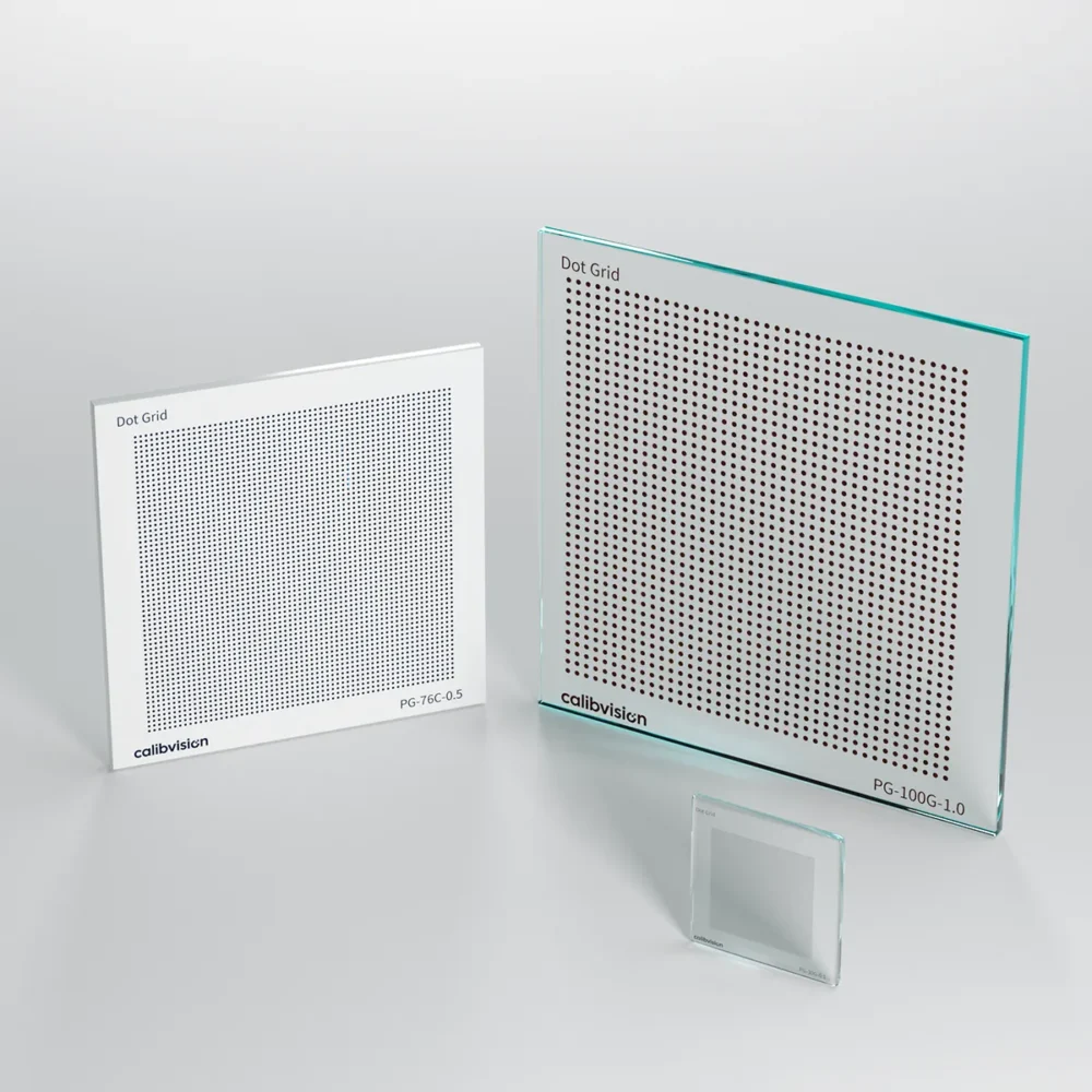
Circle grids are the VisionMark Pro (PG-) dot-grid series — model number PG-[size + substrate]-[dot mm]-[chrome], 15–250 mm, ±0.5–2 µm. Specify a symmetric or asymmetric arrangement, dot diameter and spacing when you order; asymmetric grids for OpenCV are made to your patternSize. Full options are on the dot grid target page.
How do I order the right circle grid?
Tell us your software, camera and lens, working distance, and whether you need a symmetric or asymmetric layout — or the patternSize you are targeting — and our engineers will specify dot size, spacing and substrate. Standard targets ship in 4–6 working days with a dimensional inspection report.