SO 16505 is the standard for camera monitor systems (CMS) — the camera-and-display systems that replace a vehicle’s rear-view and side mirrors. Because a CMS is safety-critical and road-legal only if it meets ISO 16505 (alongside ECE R46 and GB 15084), its image quality is tested rigorously, and resolution is measured with an SFR chart. The key thing to understand is that ISO 16505 tests the resolution of the entire camera-to-monitor chain, not just the camera. This guide covers how that end-to-end measurement works, the SFR chart’s design, the spatial-frequency unit that confuses newcomers, and how ISO 16505 differs from ISO 12233.
What is a camera monitor system, and why ISO 16505?
A CMS uses a camera and an in-cabin display to give the driver the view a mirror used to provide. Regulators treat it as a safety device: it must show enough detail, at enough contrast, across a defined field, under day and night conditions. ISO 16505 (current edition 2019) sets those requirements and the test procedures to verify them, and type approval under ECE R46 references it. If a CMS fails its ISO 16505 resolution requirement, it cannot legally replace a mirror.
The key difference: you measure the whole chain
In a normal camera test you photograph a chart and analyse the image file. A CMS has no accessible image file at the point that matters — the driver sees a monitor. So ISO 16505 measures the complete path: the CMS camera images the chart, the CMS renders it on its display, and a second measurement camera photographs that display. The SFR you compute is end-to-end — camera optics, sensor, processing, and the monitor together — because that is what the driver actually sees.
The SFR chart and why it sits on an 18% gray background
The ISO 16505 SFR chart uses slanted edges — the same slanted-edge SFR technique as ISO 12233, where a tilted high-contrast edge is super-sampled to recover a fine edge profile and transform it into an MTF curve. The chart carries several slanted-edge blocks, each with both horizontal and vertical edges so you get MTF in both directions and at several field positions.
What is specific to ISO 16505 is the 18% gray background. A CMS runs its own automatic exposure and gain, exactly as it would on the road. The 18% mid-gray field drives that auto-exposure to a correct, repeatable operating point, so the SFR is measured with the system exposed the way it actually behaves — not saturated by a white field or crushed by a black one. The surface is matte for the same reason it matters on any measurement chart: glare would corrupt the edge.
The spatial-frequency unit that trips people up
ISO 16505 reports MTF in LW/PH — line widths per (effective) picture height. This is deliberate: expressing the frequency relative to picture height lets the image inside the CMS (the camera output) and the image of the monitor (what the measurement camera captures) be compared on the same scale, even though they are different pixel grids. It is a common source of confusion — if your numbers look an order of magnitude off, check whether you are mixing cycles/pixel with LW/PH.
ISO 16505 is a bundle, not one chart
Resolution is only one of the image-quality factors ISO 16505 defines, and each has its own chart. A full CMS evaluation uses a set:
| Chart | Measures |
|---|---|
| SFR (slanted edge) | Resolution / MTF |
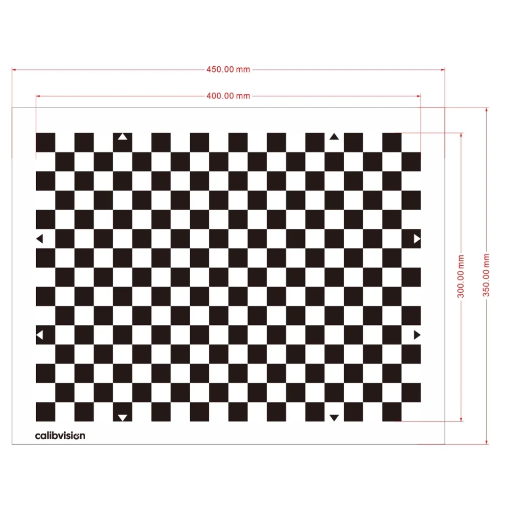
| Distortion / magnification (grid or checkerboard) | Geometric distortion, minimum magnification across the field |
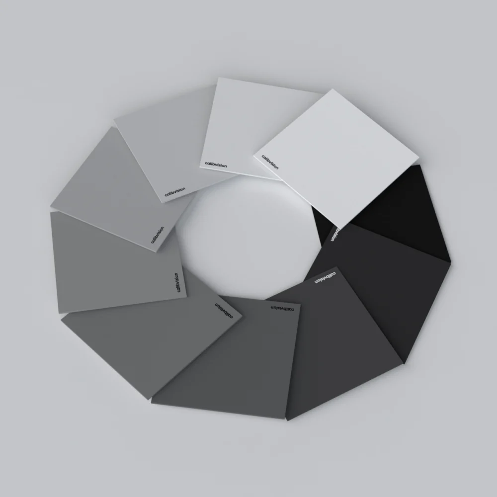
| OECF / grayscale (per ISO 14524) | Tone transfer, luminance |
| Color | Color reproduction (an 8-color, ColorChecker-style layout) |
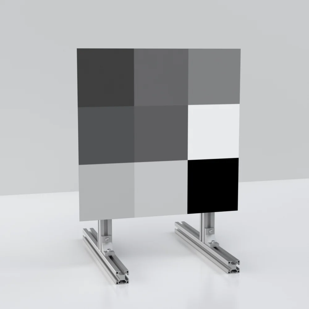
| Gray 18% / 70% | Single-tone uniformity (>98%) |
For the tone-transfer side, the OECF is the same concept covered in ISO 15739 noise and dynamic range testing; the diffuse, matte gray fields rely on the same Lambertian behaviour that makes reflectance standards reliable.
Requirements vary across the field
A mirror shows more detail near the centre of the field than at the edges, and ISO 16505 mirrors that: its resolution and magnification requirements are field-dependent, specified at defined positions rather than as a single number. This is why the SFR chart places edge blocks across the field and why a CMS can pass at the centre yet fail toward the periphery — the test is designed to catch exactly that.
ISO 16505 vs ISO 12233
| ISO 12233 | ISO 16505 | |
|---|---|---|
| Device | A digital camera | A camera monitor system (camera + display) |
| What’s measured | Camera image (file) | End-to-end, via a second camera on the monitor |
| Method | Slanted-edge SFR | Slanted-edge SFR, on 18% gray, in LW/PH |
| Context | General imaging | Automotive mirror-replacement, road-legal |
They share the slanted-edge method but answer different questions. For the general resolution chart, see the ISO 12233 chart comparison; for the automotive sensing side more broadly, the LiDAR reflectance guide covers the other half of ADAS perception validation.
The CalibVision ISO 16505 SFR chart
CalibVision’s ISO 16505 SFR chart follows the standard’s design — multiple high-contrast slanted-edge blocks on a matte 18% gray background, giving horizontal and vertical MTF across the field, and analysable in the usual SFR software. Sizes and layouts are available to the standard or customised to your CMS field and working distance, and the matching charts for the rest of the ISO 16505 bundle — distortion, OECF, color and gray — can be supplied together. Every chart ships with a serial-numbered inspection report; measurements are NIST/NIM-traceable, with product-level traceability under CNAS L0579 and ILAC-MRA, and third-party CNAS/ILAC calibration on request.
How do I order the right ISO 16505 charts?
Tell us your CMS field of view, the measurement geometry and which image-quality factors you need to certify — SFR alone or the full bundle — and our engineers will specify the charts and sizes. Standard charts ship with a documented, serial-numbered inspection report.