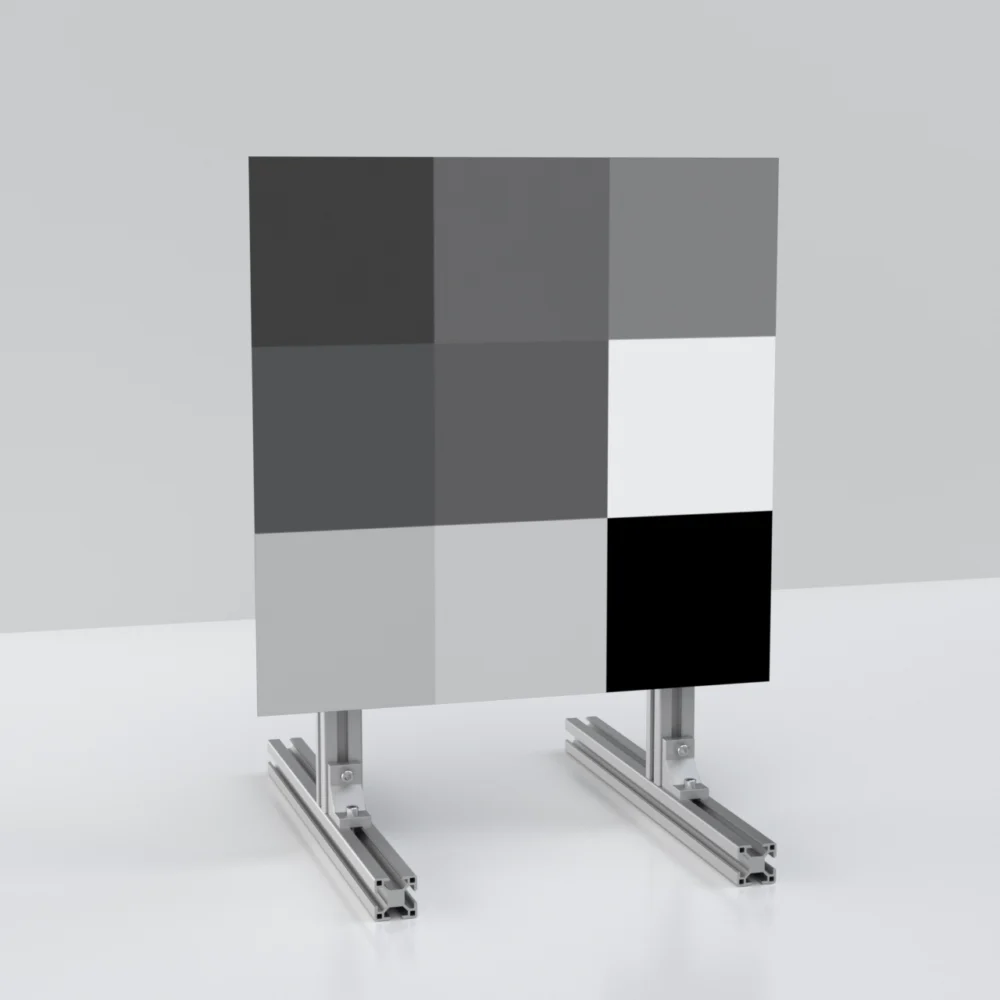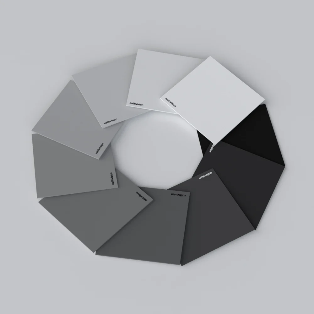
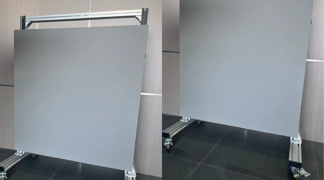
A lidar can pass its range test on a 10% target and still be late seeing a tire lying in the lane. Tires, matte black bumpers and dark clothing often return less light than the 10% panel most test kits are built around. Checking that part of the performance envelope takes a darker target.
A low-reflectivity lidar target is a flat, diffuse (near-Lambertian) panel whose reflectance is calibrated below 10%, typically 3% or 5%, at the lidar’s own wavelength: 905 nm, 1550 nm, or both. It is used to measure how far a lidar can reliably detect dark objects.
Building one is harder than it looks. At 3%, the tolerance, the surface gloss, the wavelength behavior and even the mounting screws have a bigger effect on the result than they do at 10% or 50%. The sections below work through what changes at low reflectivity, how much range to expect, and what to put in the specification.
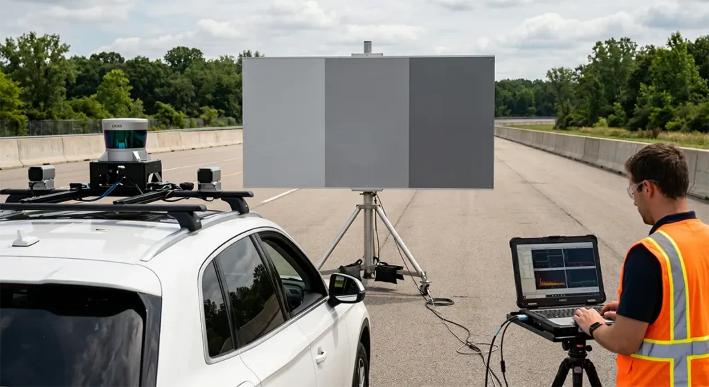
Why 10% Is Not the Darkest Thing on the Road
Lidar range is usually quoted at 10% reflectivity. Hesai describes ranging capability as the farthest detection distance under standard working conditions, with the 10% target as the reference, and uses a black tire as the everyday example of a roughly 10% object.
Cepton puts the tire lower: “A black tire’s reflectivity is normally below 10%, and that’s why we use black tire detection to benchmark lidar performance.” The same article ranks common objects as black tire < black car < white car.
Dark paint is the other well-documented case. Conventional dark automotive pigments are based on carbon black, which “absorbs not only visible light but also NIR, making it difficult to sense in LiDAR,” as a 2023 paper on lidar-detectable coatings puts it.
So 10% is the reference point for a spec sheet, not the floor of what a lidar meets on the road. Common target sets follow the same convention: the test bench that Ansys describes for DIN SAE SPEC 91471 uses 10%, 50% and 80% Lambertian targets. A test plan that stops at 10% has no measured data on how the sensor behaves below it. That gap is what 3% and 5% targets are for.
How Much Range a LiDAR Loses at 3% and 5%
For a diffuse target larger than the laser spot, the simplified lidar equation makes received power proportional to target reflectivity and inversely proportional to the square of distance. LeddarTech’s tech note gives it as Pr = Pt × ρ × A0 / (πR²) × η0 × exp(−2Rγ), assuming normal incidence, Lambertian reflection, a flat beam profile and negligible divergence.
If the detection threshold stays the same and atmospheric loss is ignored, maximum range scales with the square root of reflectivity. Cepton’s published example follows the same rule: 250 m at 10% represents the same detection capability as 500 m at 40% or 750 m at 90%.
Applying the square-root rule downward gives a quick estimate:
| Rated range at 10% | Estimated at 5% | Estimated at 3% | Estimated at 2% |
|---|---|---|---|
| 150 m | 106 m | 82 m | 67 m |
| 200 m | 141 m | 110 m | 89 m |
| 250 m | 177 m | 137 m | 112 m |
| 300 m | 212 m | 164 m | 134 m |
Table 1. Estimated detection range at low reflectivity, scaled from the 10% rating by the square root of the reflectivity ratio. Assumes an extended Lambertian target at normal incidence, the same detection threshold, and no atmospheric loss.
A lidar rated for 200 m at 10% should be expected to detect a 3% target at roughly 110 m, about 55% of its rated range.
These are planning numbers. Real sensors deviate because of receiver noise, weather and the required detection probability, which Cepton notes most OEMs set at 90% or 95%. That is the reason to measure with a calibrated 3% or 5% target instead of extrapolating from the 10% result.
What Makes a 3% Target Harder to Build Than a 10% Target
Reflectance tolerance is normally stated in absolute points. ±0.3% on a 3% target is ±10% of the value, and through the square-root rule that becomes about ±5% in measured range. Loosen the tolerance to ±1% and the same nominal 3% target could sit anywhere from 2% to 4%.
| Nominal | Tolerance | Possible reflectance | Effect on expected range |
|---|---|---|---|
| 3% | ±0.3% | 2.7% to 3.3% | about ±5% |
| 3% | ±0.5% | 2.5% to 3.5% | −9% to +8% |
| 3% | ±1% | 2% to 4% | −18% to +15% |
| 10% | ±1% | 9% to 11% | about ±5% |
Table 2. How reflectance tolerance carries through to range, using the square-root rule from Table 1.
A tolerance that is routine at 10% has to be about three times tighter at 3% to give the same confidence in the range result.
Gloss can outweigh the diffuse reflectance
A smooth coating with a refractive index near 1.5 reflects about 4% of light from its surface at normal incidence. This is Fresnel reflection, and it happens before any pigment is involved. That mirror-like component alone is larger than the 3% the target is supposed to return.
A lidar pointed straight at a glossy black panel can read far above nominal, and the reading drops sharply as soon as the panel is tilted. A low-reflectivity target needs a matte, diffuse surface, so the return follows the Lambertian cosine law instead of depending on a specular highlight.
Black to the eye is not always dark to a lidar
Visible appearance says little about 905 nm or 1550 nm. On ST’s sensor forum, an ST engineer explained why a gray card printed on an office printer fails as a 940 nm reference: printer ink is a dye that 940 nm light passes straight through, so it does not change the reflectance of the paper underneath.
Many black inks, plastics and fabrics behave in a similar way and return more near-infrared light than their appearance suggests. A 3% target has to be measured at the wavelength the lidar uses. If one panel serves both a 905 nm and a 1550 nm sensor, it needs a measured value at each.
Dust and fingerprints show up sooner
On a 3% surface, a film of dust or a fingerprint can reflect more than the coating itself. Handle the face with clean gloves, keep it covered between tests, and remove light dust with a soft brush. Ask for uniformity data measured at several points across the panel as well, because a large panel is sampled by many beams, not one.
How Large the Target Needs to Be
Two conditions set the minimum size. The panel must be larger than the laser spot at the test distance, otherwise part of the beam passes the edge and returns from the background. And enough scan points must land on the panel to work out a detection probability.
Point spacing is distance × tan(angular resolution). For a lidar with 0.1° resolution:
| Distance | Point spacing at 0.1° | Whole points across a 1.2 m panel |
|---|---|---|
| 50 m | 8.7 cm | 13 |
| 100 m | 17.5 cm | 6 |
| 150 m | 26.2 cm | 4 |
| 200 m | 34.9 cm | 3 |
Table 3. Point spacing and points per row on a 1.2 m (48″) wide panel. 0.1° is an illustrative figure; substitute your sensor’s horizontal and vertical resolution.
Low-reflectivity tests usually run at shorter distances than 10% tests, because range falls with reflectivity. That works in the target’s favor: a 1.2 m panel that is marginal at 200 m collects a usable grid of points at 100 m.
Edges deserve more care on a dark target. A beam that straddles the edge mixes the 3% return with whatever is behind the panel, and almost any background is brighter than 3%.
Mounting: Keep Bright Hardware Off the Target Face
On a 50% target, a screw head on the face is a minor blemish. On a 3% target, bare metal, a white label or an exposed frame edge can return more light than the coated area around it.
Three practical rules follow:
- Mount from the rear. Threaded inserts installed in the back of the panel let the frame hold it without any fastener breaking the coated face.
- Hide the frame. Keep frame members behind the panel outline, or finish any exposed parts in the same low-reflectivity coating.
- Control the background. Open sky or a dark absorbing surface behind the target keeps edge returns from being counted as the target.
A rigid, flat substrate matters as well. Aluminum honeycomb is a common choice at 1 m and larger because it is stiff for its weight, which helps the whole face sit at one distance and one angle to the sensor.
What to Specify When You Order
A low-reflectivity target is usually made to order. These are the points a supplier needs, and the reason each one matters:
| Item | What to state | Why it matters |
|---|---|---|
| Reflectance and tolerance | For example, 3% ±0.3% | Tolerance converts directly into range uncertainty |
| Wavelength | 905 nm, 1550 nm, or both | Reflectance must be measured where the lidar operates |
| Size | Width × height, such as 1219.2 × 1219.2 mm (48″ × 48″) | Sets the usable test distance |
| Substrate and thickness | Such as aluminum honeycomb, 15 mm | Flatness, stiffness and weight |
| Mounting | Insert thread, quantity and positions, and whether the drawing shows the front or the rear | Must match your frame, with no hardware on the face |
| Surface | Matte, diffuse, coated over the entire face | Avoids specular returns and bright borders |
| Test report | Measured reflectance per panel at each wavelength, with uniformity points | Evidence for your own test records |
| Quantity and delivery | Number of panels, required date, destination | Large panels ship crated, which affects freight time |
Table 4. Specification checklist for a custom low-reflectivity lidar target.
If you have a frame drawing, send it. Hole positions on large panels are often not symmetric, and stating whether the drawing shows the front or the rear avoids a mirrored pattern.
How Calibvision Builds Low-Reflectivity Targets
Calibvision makes diffuse reflectance targets to order, including low-reflectivity panels for lidar testing. A typical configuration looks like this:
- 3% ±0.3% reflectance at both 905 nm and 1550 nm, with the diffuse coating over the entire face
- 1219.2 × 1219.2 mm (48″ × 48″) aluminum honeycomb panel, 15 mm thick
- M8 threaded inserts pre-installed on the rear, positioned to the customer’s frame drawing
- A measured reflectance report supplied with each panel at both wavelengths
- Wooden crate packing for shipment
Other reflectance levels, sizes and mounting patterns are built the same way.
Send us your wavelength, reflectance level, panel size and frame drawing, and we will confirm the achievable tolerance and quote the set.
CTA 按钮: Send Your Specs / Get a Target Quote → 链接到 https://calibvision.com/custom-quote/
Frequently asked questions
What counts as low reflectivity for lidar testing?
Anything below the 10% level that range specifications are quoted at. 3% and 5% are typical choices for dark-object tests.
How far can a lidar detect a 3% target?
As a planning estimate, about 55% of its rated range at 10%. A lidar rated for 200 m at 10% would be expected to reach roughly 110 m on a 3% target. The measured figure depends on the sensor’s noise, the required detection probability and the weather.
Can black paint, cardboard or fabric stand in for a low-reflectivity target?
For a quick functional check, yes. For a range claim, no. The reflectance at 905 nm or 1550 nm is unknown and may differ a lot from how the material looks, and gloss and unevenness change the return from point to point.
Does a 3% target at 905 nm also measure 3% at 1550 nm?
Not automatically. Reflectance depends on the coating and the wavelength. If the target will be used with both lidar types, specify both wavelengths and ask for a measured value at each.
What tolerance should I ask for on a 3% target?
±0.3% keeps the target’s contribution to range uncertainty to about ±5%. A ±1% tolerance on a 3% target allows roughly −18% to +15%.
How should the target face the lidar?
Square to the sensor, unless the test plan calls for an angle. The return from a diffuse surface falls with the cosine of the incidence angle, so a tilted panel reads lower than its nominal value.
How should a low-reflectivity target be cleaned and stored?
Do not touch the coated face with bare hands or liquids. Wear clean gloves, remove light dust with a soft brush, and keep the panel covered or in its crate when it is not in use.