If you calibrate in MVTec HALCON, you are not using a checkerboard — you are using a calibration plate of circular marks, the pattern HALCON’s calibration is built around. Three things make it work: a description file that defines the plate geometry, an ellipse fit of each mark that corrects for perspective, and a finder pattern that fixes the origin and orientation. This guide covers how that workflow runs, the difference between classic fully-visible plates and newer partial-view plates, why a third-party plate needs a matching description file, and how substrate sets accuracy.
How does a HALCON calibration plate work?
HALCON detects the centre of every circular mark, matches the detected marks to their known positions from the plate’s description, and solves for the camera model. In modern HALCON the workflow is:
create_calib_data ('calibration_object', 1, 1, CalibDataID)
set_calib_data_calib_object (CalibDataID, 0, 'my_plate.descr')   * plate geometry
for Index := 1 to NumImages by 1
    find_calib_object (Image, CalibDataID, 0, 0, Index, [], [])   * detect marks + pose
endfor
calibrate_cameras (CalibDataID, Error)
get_calib_data (CalibDataID, 'camera', 0, 'params', CamParam)
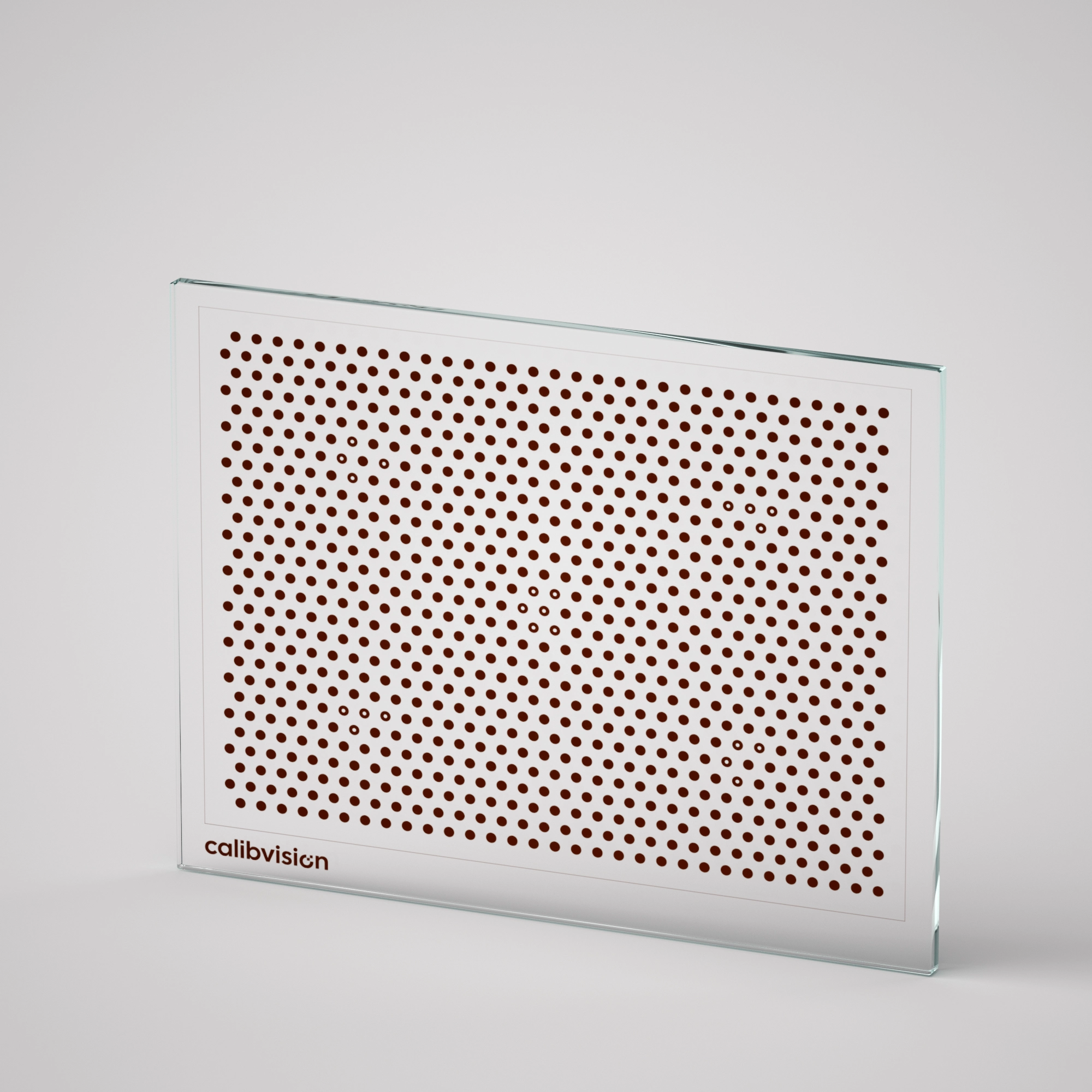
The single most important input is the .descr description file (the “caltab” file). It lists the exact position of every mark and describes the finder pattern, so HALCON knows both the metric geometry and which way is up. Everything else depends on it being correct.
Why does HALCON use circular marks instead of corners?
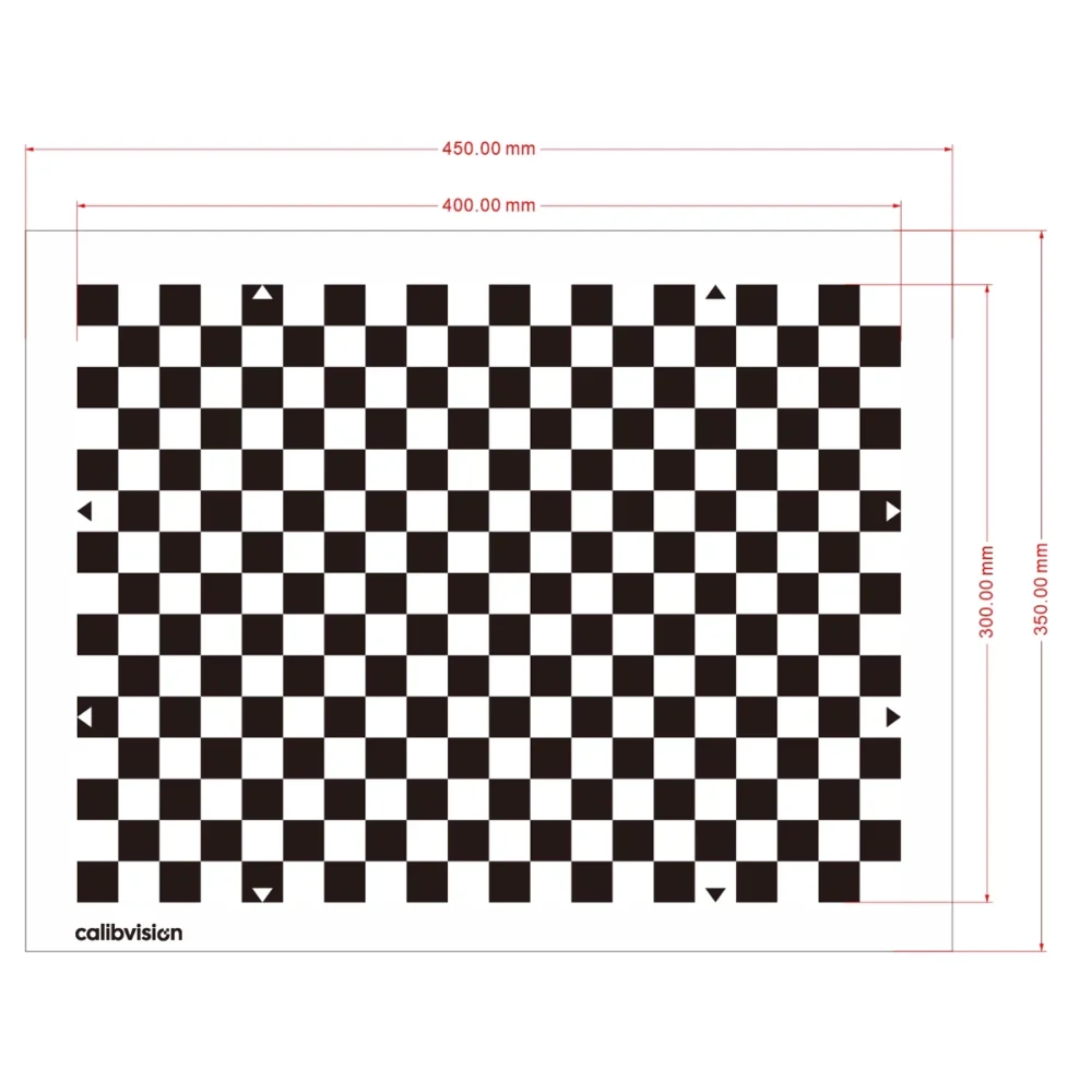
A circular mark can be located to very low noise, because HALCON fits an ellipse to many edge pixels rather than intersecting two lines. The catch is that a circle images to an ellipse under perspective, and the ellipse’s centroid is not the true projected centre — a systematic bias. HALCON’s calibration models this and corrects it, which is exactly why the dot plate delivers metrology-grade accuracy in that ecosystem where a naive centroid would not. For the full corner-versus-centroid picture, see checkerboard vs dot grid.
Classic plate vs partial-view plate
Two generations of plate exist, and it matters which your workflow expects:
- Classic plate — marks in a rectangular arrangement with a surrounding frame and a single triangular corner marker. It must be fully visible in every calibration image.
- Newer plate (HALCON 12 and later) — a denser field of marks with finder patterns that does not need to be completely visible. This simplifies multi-view calibration and placing the plate near the image border, and it reaches a good result with fewer images because each view carries more marks.
Positive or negative?
HALCON plates come in two polarities. A positive plate has opaque marks on a clear background; a negative plate has clear marks on an opaque background, which suits backlit setups where the marks read as bright dots. Choose the one your illumination and description file expect.
Using a third-party HALCON plate
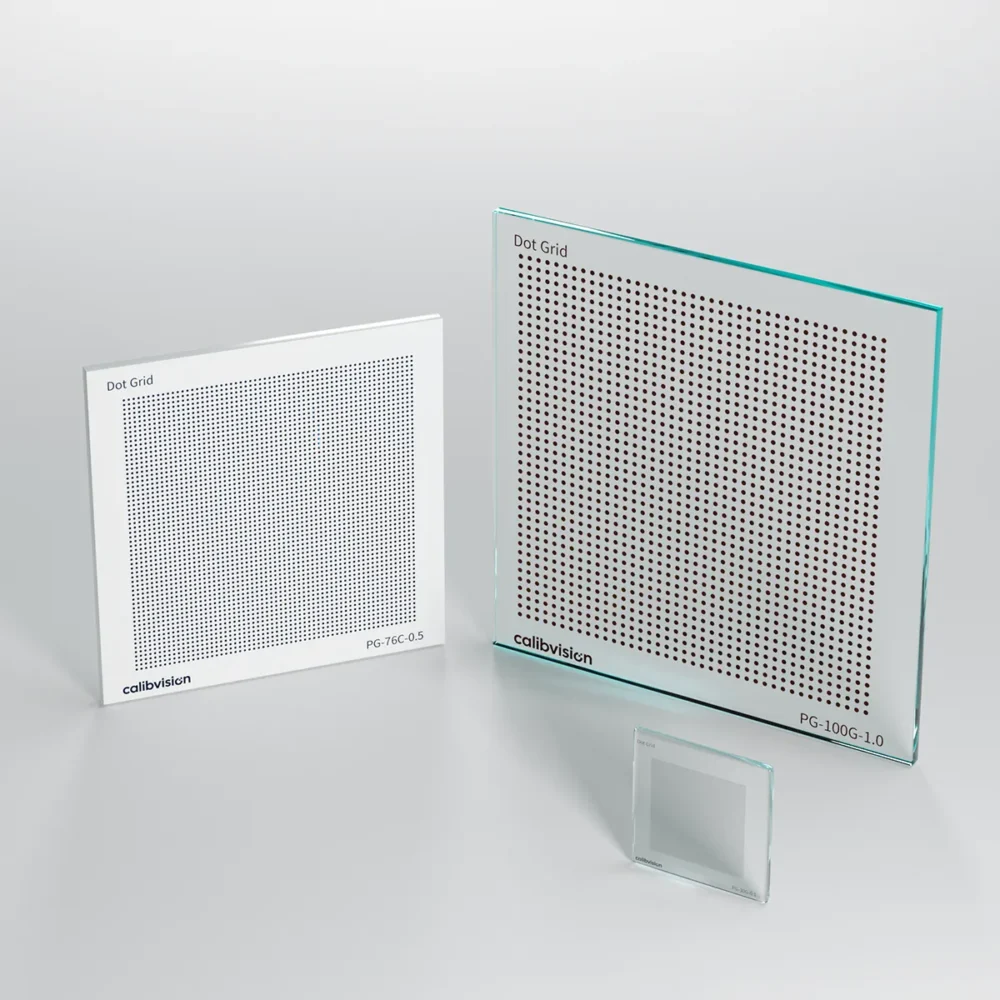
You are not limited to MVTec’s own plates — but a HALCON-compatible plate is only usable if it ships with a description file that matches its exact geometry. Order the plate, load its .descr, and — critically — verify the printed dimensions against the file before calibrating, because a scale mismatch between the physical plate and its description looks exactly like a calibration error when it isn’t one. CalibVision supplies the matching description file with every HALCON plate.
Substrate and accuracy
The substrate sets the accuracy tier and the illumination fit:
| Substrate | Feature accuracy | Best for |
|---|---|---|
| Quartz glass | ±0.5 µm | Metrology, thermal/UV, backlit |
| Soda-lime glass | ±1 µm | Backlit precision machine vision |
| Matte ceramic | ±2 µm | Front-lit, rugged production floors |
As with any target, the plate sets your accuracy ceiling — a printed HALCON plate carries ±50–200 µm of error and warps, both of which propagate into the camera model. See how we measure and report target accuracy for what a trustworthy report must show.
Which HALCON plates are in stock?
HALCON 12 plates are the VisionMark Elite (VME-) series — a 13×15 mark array read directly from the model number: VME-[active size + substrate]-[dot mm]-[P/N], where SG is soda-lime glass, C is ceramic, QG is quartz, and P/N is positive or negative polarity. Active areas run 8.5×6.5 to 183×120 mm; dot spacing is twice the dot diameter.
| Model | Substrate | Active area | Dot | Accuracy |
|---|---|---|---|---|
| VME-35SG-1.0-P | Soda-lime · positive | 35×25 mm | 1.0 mm | ±1 µm |
| VME-100SG-3.0-P | Soda-lime · positive | 100×75 mm | 3.0 mm | ±1 µm |
| VME-50C-1.5-P | Ceramic · positive | 50×37 mm | 1.5 mm | ±2 µm |
| VME-35QG-1.0-P | Quartz · positive | 35×25 mm | 1.0 mm | ±0.5 µm |
Full list, polarities and options are on the HALCON 12 plate page; for the standard HALCON dot pattern, see the dot grid targets.
Acceptance for German and EU customers
MVTec is a German company, and HALCON users are often in Germany or the wider EU, where dimensional traceability is expected. CalibVision’s product-level traceability is accredited under CNAS L0579; through the ILAC-MRA, that accreditation is mutually recognised with DAkkS and other European signatories, so a CalibVision inspection report is accepted on the same footing as a locally accredited one. Independent third-party CNAS/ILAC calibration is available on request.
How do I order the right HALCON plate?
Tell us your HALCON version, working distance and field of view, plus substrate and polarity — or send your plate description and we will match it. Every HALCON plate ships with its matching description file and a serial-numbered inspection report.