A camera calibration target is a precisely patterned plate that gives a camera a field of reference points whose geometry is known in advance. Software locates those points across several views, compares where they landed against where they should be, and solves for the camera model that corrects lens distortion and enables accurate measurement. Choosing a target comes down to four decisions — pattern type, substrate and accuracy, physical size, and toolchain fit — and one principle underpins all of them: the target, not the algorithm, sets your accuracy ceiling.
This is a navigational overview. Each section states the decision and links to the in-depth guide where the detail lives.
Why the target sets your accuracy ceiling
Every calibration assumes the target’s geometry is exactly as specified. If the pattern is placed to ±10 µm, no camera or algorithm can recover better than about ±10 µm. A laser-printed paper target carries ±50–200 µm of positional error and warps, and both propagate straight into the result. This is why a certified, dimensionally stable target matters as much as the software — and why the accuracy figure on the datasheet is the number that actually bounds your system.
Which pattern should you use?
Four pattern families cover almost all camera calibration. The short version:
| Pattern | Feature | Best for |
|---|---|---|
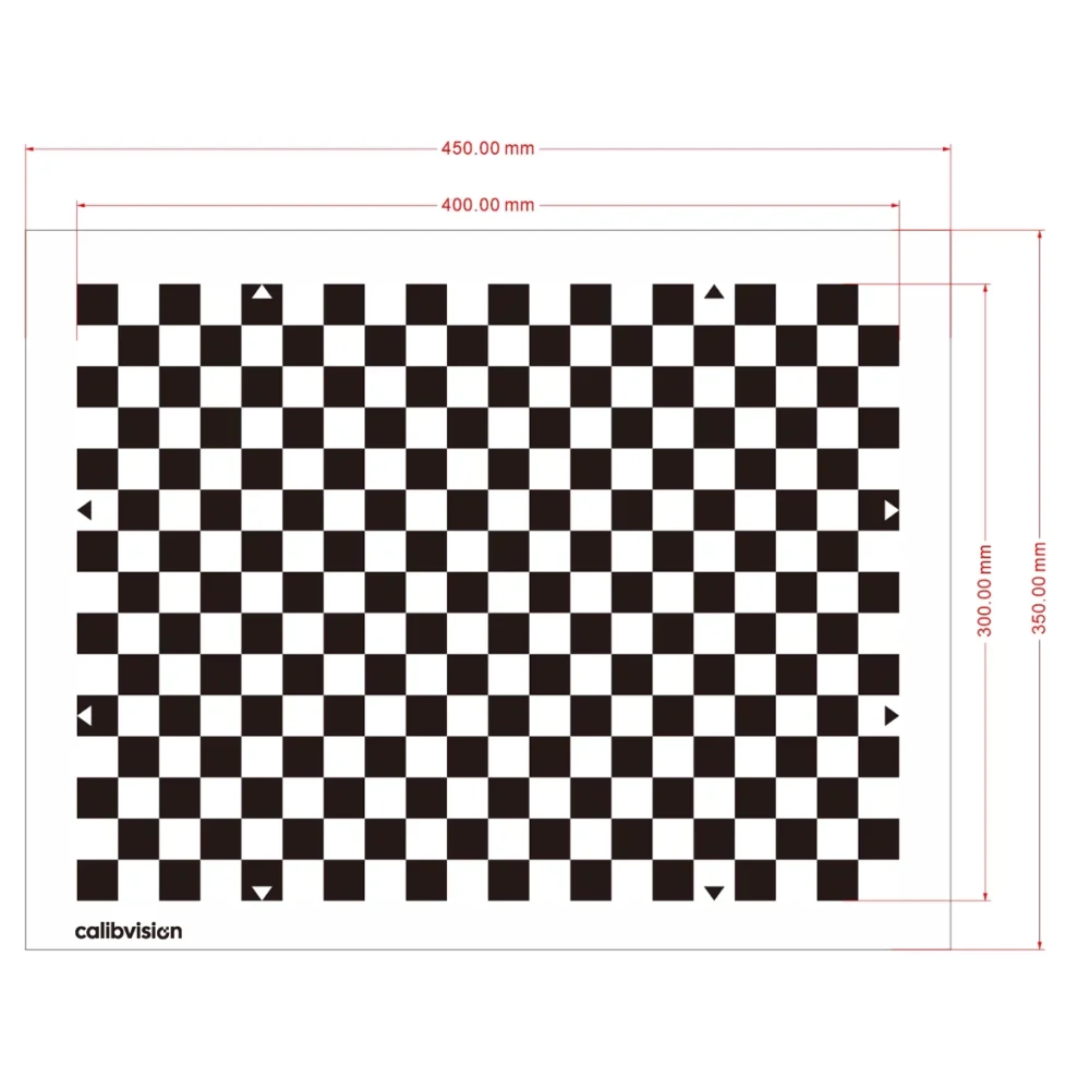
| Checkerboard | Saddle corners (unbiased) | OpenCV / MATLAB, full board in view |
| ChArUco | Corners + coded ArUco markers | Wide-angle, multi-camera, partial views (OpenCV) |
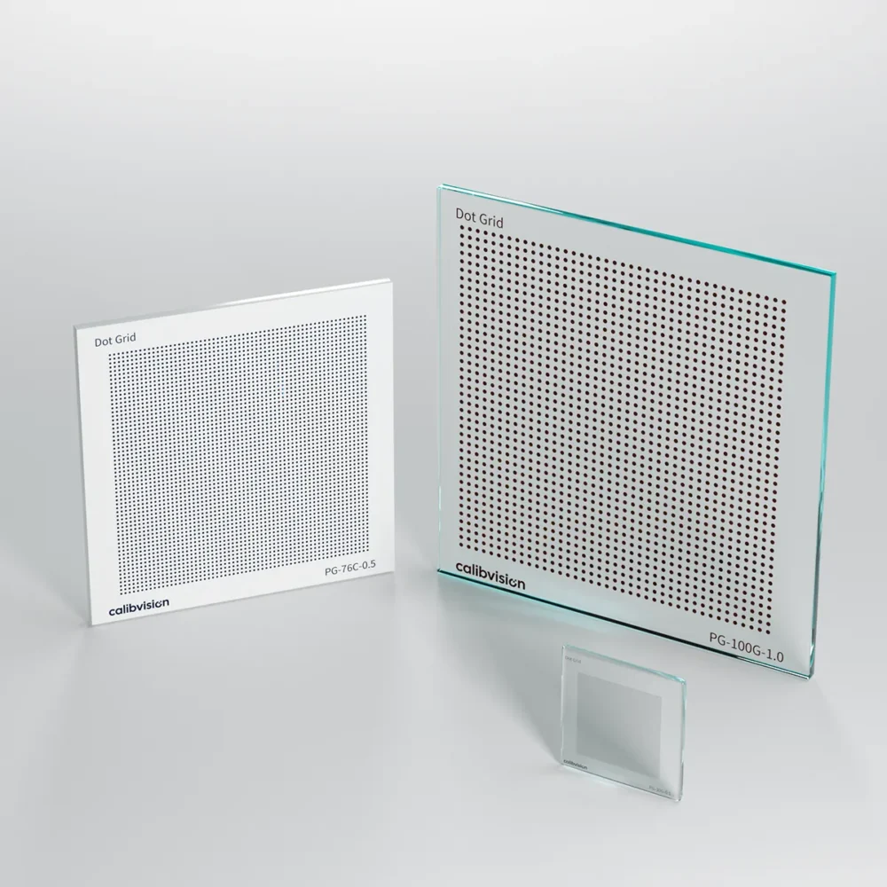
| Dot grid | Dot centroids (dense, low-noise) | HALCON metrology (CALTAB), backlit |
| AprilGrid | Coded AprilTags | ROS / Kalibr, camera-IMU, multi-sensor |
For the full comparison of feature types and coding, see calibration pattern types; for the corner-versus-centroid detail, checkerboard vs dot grid; and the deep guides for ChArUco boards and AprilGrid targets.
What substrate and accuracy do you need?
Substrate sets both the accuracy tier and the illumination fit — transparent glass for backlit setups, matte ceramic for front-lit ones.
| Substrate | Feature accuracy | Illumination | Best for |
|---|---|---|---|
| Quartz glass (blue chrome) | ±0.5 µm | Backlit | Metrology, thermal/UV, microscopy |
| Soda-lime glass (brown chrome) | ±1 µm | Backlit | Precision machine vision |
| Matte ceramic (blue chrome) | ±2 µm | Front-lit | Rugged production floors |
| Film | ±15 µm | Backlit | Large-format, portable field rigs |
| Photo paper | ±0.1–0.2 mm | Front-lit | Prototyping, budget |
Glass reaches the highest accuracy and suits backlit and transmissive work; ceramic is rugged and non-reflective for front-lit production floors; quartz adds thermal and UV stability for metrology. Film and paper cover large-format and budget use where their looser tolerances are acceptable.
How big should the target be?
Size the target so it fills roughly one-third to two-thirds of the frame at your working distance, while still fitting in view from oblique angles — you need tilted views for a good distortion estimate. As a starting point:
FOV_width ≈ 2 × working_distance × tan(horizontal_AOV / 2)
target_width ≈ 0.3 – 0.7 × FOV_width
Above all, the target must be flat: any bow is absorbed into the model as false lens distortion, so a rigid substrate matters as much as the pattern. For OpenCV specifically, the inner-corner count and square size have their own rules — see best checkerboard size for OpenCV.
Which software are you using?
Toolchain usually decides the pattern, because each ecosystem is built around one:
| Software | Pattern |
|---|---|
| OpenCV | Checkerboard or circle grid (ChArUco for partial views) |
| MATLAB | Checkerboard, circles, ChArUco |
| MVTec HALCON | Dot grid (CALTAB) |
| ROS / Kalibr | AprilGrid |
How to choose — a quick selection guide
| Application | Pattern | Substrate | Accuracy |
|---|---|---|---|
| Industrial inspection (front-lit) | Checkerboard / dot grid | Matte ceramic | ±2 µm |
| Backlit precision machine vision | Checkerboard / dot grid | Soda-lime glass | ±1 µm |
| Metrology / microscopy | Dot grid | Quartz glass | ±0.5 µm |
| Wide-angle / multi-camera (OpenCV) | ChArUco | Glass or ceramic | ±0.5–2 µm |
| Robotics, camera-IMU (ROS) | AprilGrid | Glass / film | ±0.5–15 µm |
CalibVision calibration target lines
All lines are standard, in-stock, and read directly from the model number; each ships with a serial-numbered inspection report.
- ChessMark checkerboards (CM-) — chrome-on-glass and ceramic, 25–127 mm, checkers 0.1–4.0 mm, ±0.5–2 µm. View
- ChArUco boards (CH-) — coded corners for partial-view and multi-camera calibration. View
- Dot grids (PG-) — HALCON-ready dot arrays, 15–250 mm, ±0.5–2 µm. View
- AprilGrid targets (KG-) — Kalibr-ready AprilTag grids on glass, ceramic and film. View
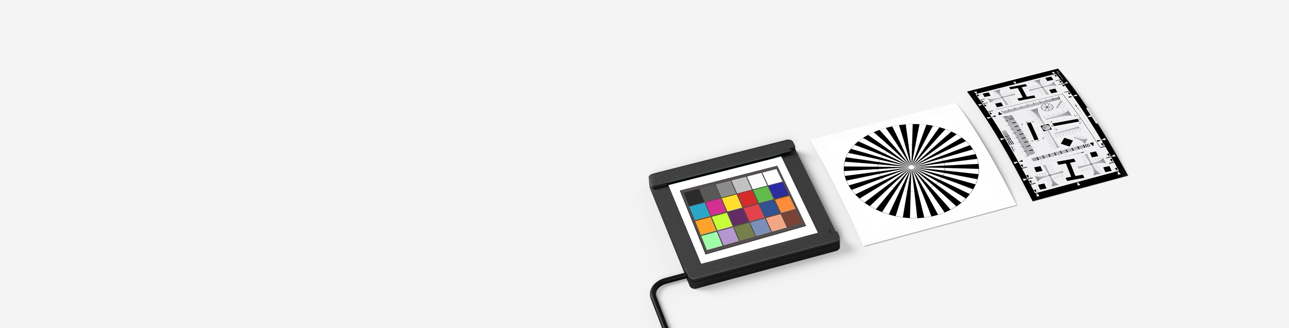
Resolution and image-quality charts — ISO 12233 e-SFR, USAF 1951, chrome-on-glass MTF, ColorChecker 24 — and diffuse reflectance standards for LiDAR are separate target families with their own guides.
How are the targets made and verified?
Precision targets are produced by photolithography: a chrome layer on glass or ceramic is laser-written, developed and etched to form clean, high-contrast features with sub-micron edge definition. Every finished target undergoes dimensional acceptance inspection and ships with a serial-numbered inspection report, so the geometry you calibrate against is the geometry that was measured. Measurements are NIST/NIM-traceable; product-level traceability is accredited under CNAS L0579 and recognised internationally through ILAC-MRA, and independent third-party CNAS/ILAC calibration is available on request. For what a trustworthy report should contain, see how we measure and report target accuracy.
How do I order the right target?
Send your software, camera and lens, working distance, illumination and accuracy target — or just describe the application and our engineers will specify the pattern, size and substrate. Standard targets ship in 4–6 working days with a dimensional inspection report.