
The slanted-edge (e-SFR) method assumes the camera responds linearly to the edge it images. A high-contrast black-to-white edge pushes the bright side into saturation and the dark side toward black, and it triggers the camera’s edge sharpening hardest — both of which inflate the measured MTF. A low-contrast edge, around 4:1 as specified in ISO 12233:2014/2017, keeps the whole edge inside the sensor’s linear range, so the MTF you measure reflects the optics, not clipping or image processing.
If you take one thing away: for ISO 12233 slanted-edge MTF, use a 4:1 contrast edge. 10:1 is a usable ceiling but sits above the standard’s preferred value, and a high-contrast (black/white) edge will give you optimistic, unreliable numbers.
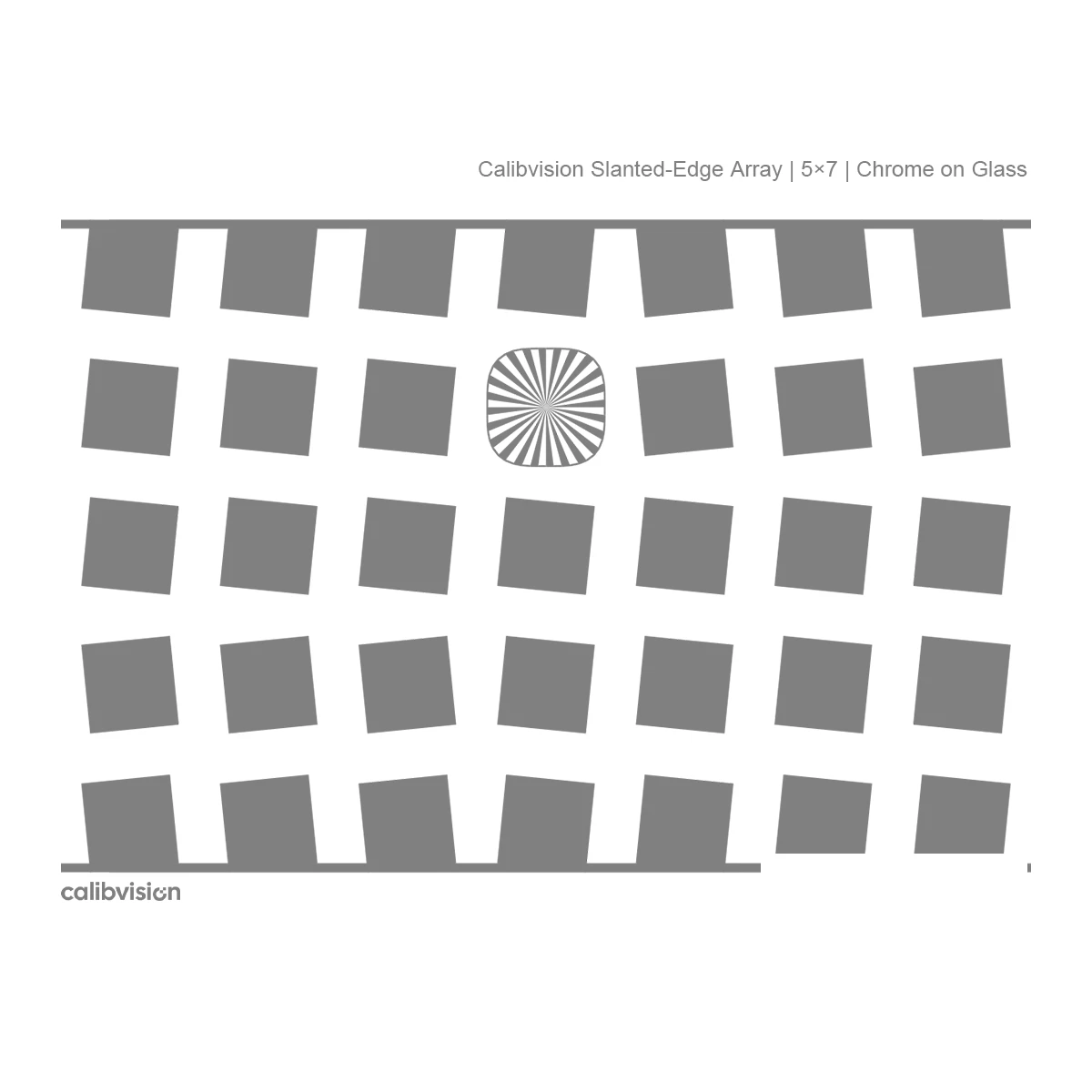
What the slanted-edge method actually measures
ISO 12233 measures spatial frequency response (SFR), the practical form of MTF, from a single slightly tilted edge:
- The camera images an edge tilted about 5° from vertical.
- The software builds a finely super-sampled edge spread function (ESF) by combining the sub-pixel edge positions across many rows.
- It differentiates the ESF to get the line spread function (LSF).
- A Fourier transform of the LSF gives the MTF.
The slant is what lets you recover detail far below the pixel pitch. But every step above is only valid if the imaging chain is linear and shift-invariant — that is, if a given amount of light always maps to a proportional pixel value.
Why contrast is the thing that breaks linearity
Real cameras are not linear by default. Three effects turn a high-contrast edge into a bad measurement:
1. Clipping / saturation. A black-to-white edge drives the white side toward the sensor’s ceiling (e.g., 255 in 8-bit) and the black side toward the floor (0). Clipped pixels flatten the tails of the ESF. A flattened ESF looks like a sharper edge than it really is, so the computed MTF is artificially high.
2. Content-adaptive sharpening. Most cameras apply edge enhancement that scales with local contrast. A high-contrast edge triggers this the hardest, so you end up measuring the image processor’s sharpening — not the lens and sensor. The result is inflated, and it changes with scene content.
3. Gamma / tone curve. Pixel values are usually gamma-encoded. The slanted-edge math needs linearized data (the OECF/gamma removed) before the ESF is built. Any residual nonlinearity is amplified when the edge spans the full tonal range, as a high-contrast edge does.
A low-contrast edge sidesteps all three: both sides sit comfortably inside the linear mid-range, the tails of the ESF are preserved, and the sharpening trigger is far weaker.
What ISO 12233 actually specifies
The 2014 revision (carried into 2017) replaced the old high-contrast bar method with the low-contrast edge SFR (e-SFR) chart. The edge is specified by:
- Edge modulation contrast of 0.55–0.65 (Michelson), which corresponds to a luminance ratio of roughly 4:1.
- A controlled mean level: the active area should integrate to a reflectance/transmittance of about 0.15–0.25, so neither side of the edge approaches clipping.
In other words, the standard cares about both the ratio between the two tones and where that pair sits on the tonal scale. It is not enough to be “low contrast” — the edge also has to be parked in the linear part of the response.
4:1 vs 10:1 vs high contrast — side by side
| High contrast (black/white) | 10:1 | 4:1 (ISO-preferred) | |
|---|---|---|---|
| Michelson modulation | ≈ 1.0 | 0.82 | 0.55–0.65 |
| Optical density difference (ΔOD) | ≈ 3.0 | 1.0 | ≈ 0.6 |
| Clipping risk | High (both ends) | Low–moderate | Very low |
| Sharpening triggered | Strongest | Moderate | Weakest |
| ISO 12233:2017 compliance | No | Above preferred value | Yes |
| Typical use | Avoid for MTF | Acceptable ceiling / higher signal | Recommended for MTF |
Where 10:1 fits: it is a practical middle ground. It avoids the worst clipping of a black/white edge and gives a bit more signal than 4:1 — useful if your illumination is weak or your pipeline is noisy. But it is above the standard’s preferred value, so report it as such. 4:1 is the reference condition.
How contrast ratio maps to modulation and optical density
These three numbers describe the same edge, which is why specs and datasheets switch between them:
- Contrast ratio (CR) = L_max / L_min
- Michelson modulation M = (CR − 1) / (CR + 1)
- Optical density difference ΔOD = log₁₀(CR)
| Contrast ratio | Modulation (M) | OD |
|---|---|---|
| 4:1 | 0.60 | 0.60 |
| 6:1 | 0.71 | 0.78 |
| 10:1 | 0.82 | 1.00 |
| 1000:1 (opaque chrome) | ≈ 1.00 | 3.00 |
This is why a standard opaque chrome target — optical density 3 to 4, i.e. ~1000:1 — is the wrong tool for slanted-edge MTF. To make a true 4:1 or 10:1 edge you need a controlled-density dark tone (ΔOD of about 0.6 to 1.0), not full opacity.
Practical recommendations
- Default to 4:1 for ISO 12233 slanted-edge MTF. It is the reference condition and gives the most accurate, repeatable numbers.
- Use 10:1 only as a ceiling, when you need extra signal — and note in your report that it is above the ISO-preferred contrast.
- Never use a black/white (high-contrast) edge for MTF. The result will look better than your optics actually are.
- Linearize first. Whatever the contrast, remove the camera’s gamma/OECF before computing the ESF.
- Watch the mean level, not just the ratio. Keep the edge centered in the linear range so neither side clips.
- Get your contrast from coating density, not from dithering. A halftone/dithered “gray” introduces structure that corrupts the edge profile. The low contrast must come from a continuous controlled-density layer.
How to source a compliant low-contrast target
Because the contrast has to come from controlled coating density rather than full opacity, the substrate matters. Two routes give a clean, grain-free low-contrast edge:
- Chrome on glass at a controlled density — laser-etched, continuous (not screened), with sub-micron edges. Well suited to 10:1.
- Optical-coating on glass — coating density is finely controllable, which makes it a good route to the low, ISO-preferred 4:1 across the full active area.
Both are photolithographic/coated processes on glass, so unlike film targets they carry no grain and no ppi limitation. (See our companion article on film vs chrome-on-glass and why grain structure matters for MTF.)
FAQ
What contrast ratio does ISO 12233 specify for slanted-edge MTF?
An edge modulation of 0.55–0.65, equivalent to about a 4:1 luminance ratio, with an active-area mean level of roughly 0.15–0.25.
Can I use a 10:1 target for ISO 12233?
Yes, as a practical ceiling. It avoids the worst clipping of a high-contrast edge but sits above the standard’s preferred 4:1, so it should be reported as a non-reference condition.
Why not just use a black-and-white edge for maximum signal?
A high-contrast edge clips at both ends and triggers the camera’s sharpening hardest. Both effects inflate the measured MTF, so the result reflects clipping and image processing rather than the lens and sensor.
Is contrast ratio the same as optical density?
No, but they are related: ΔOD = log₁₀(contrast ratio). A 4:1 edge is ΔOD ≈ 0.6; 10:1 is ΔOD = 1.0; opaque chrome is ΔOD ≈ 3 (about 1000:1).
Why is opaque chrome unsuitable for low-contrast MTF targets?
Opaque chrome is roughly 1000:1 contrast — far too high. A true 4:1 or 10:1 edge needs a controlled partial-density coating, not full opacity.

One Response