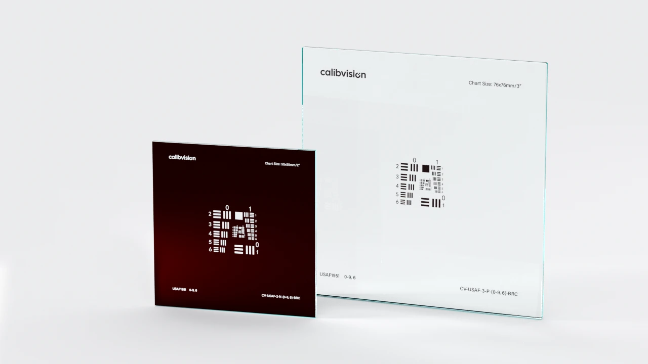
When it comes to testing optical systems, one tool has stood the test of time for over 70 years. The USAF1951 resolution test chart remains the industry standard for measuring the resolving power of lenses, cameras, and entire imaging systems.
But what exactly is this pattern of black bars, and how do you use it? This guide breaks down everything you need to know about the USAF1951 test target – from its origins to practical applications in today’s advanced imaging systems.
What is a USAF1951 Test Target?
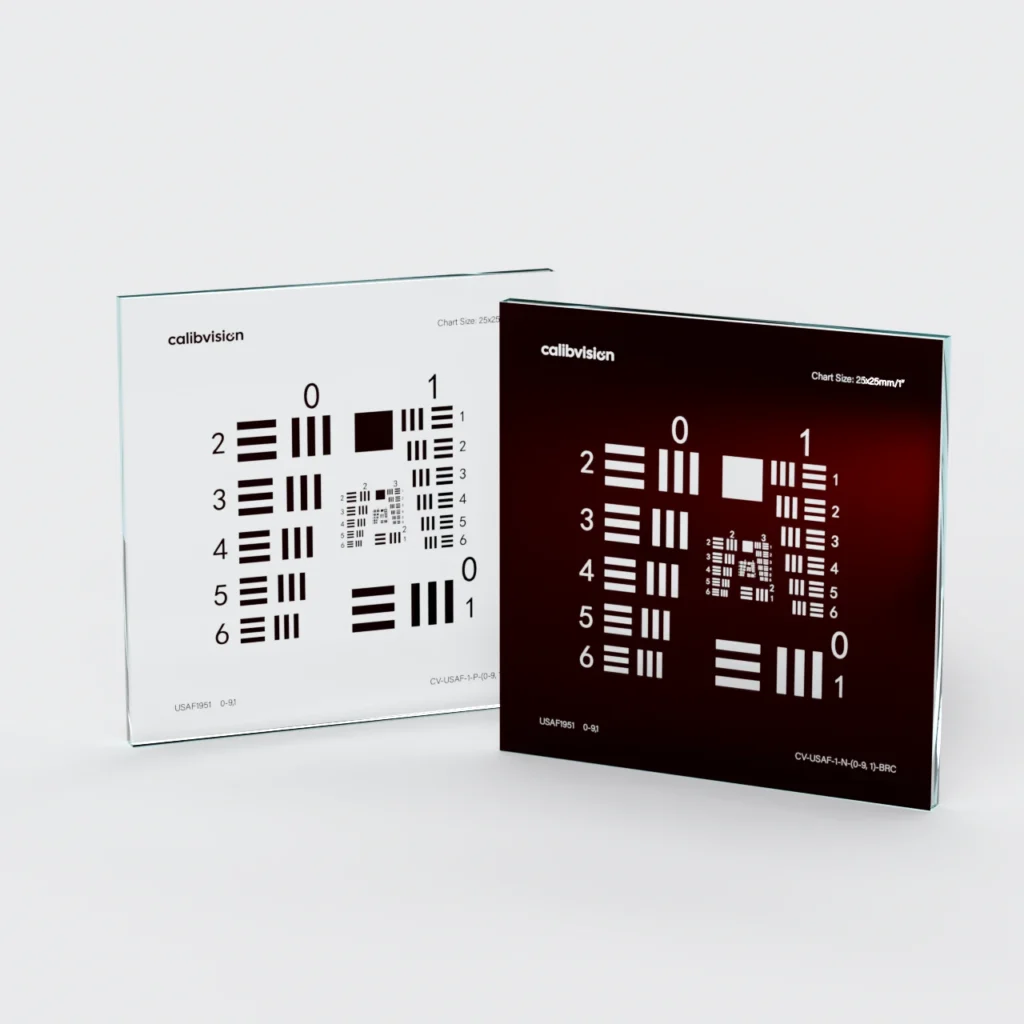
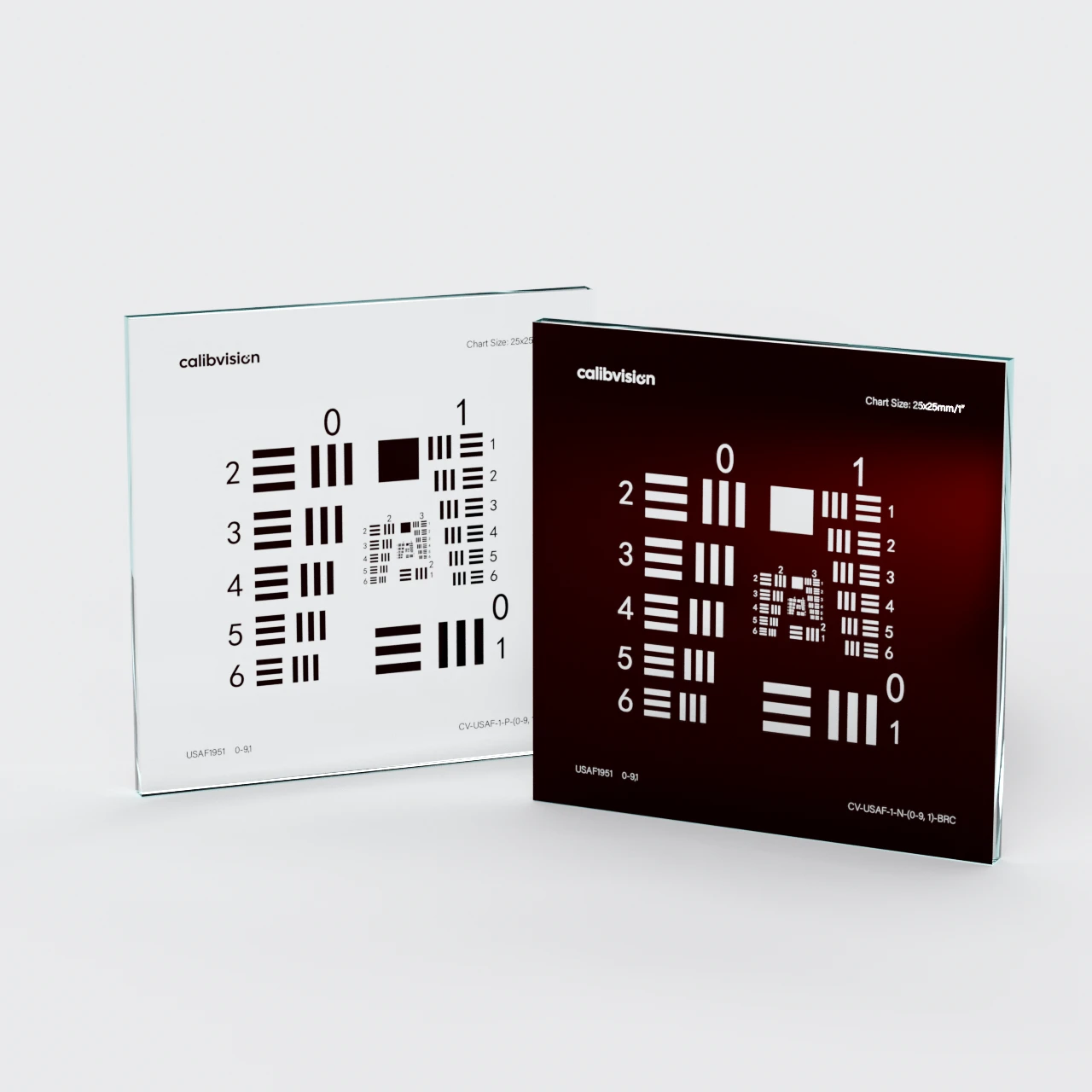
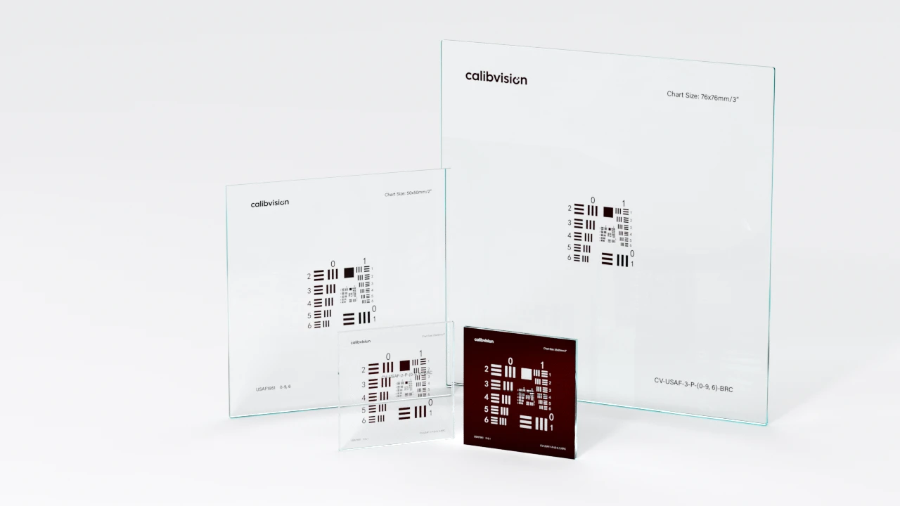
A USAF1951 test target is a standardized resolution test pattern originally developed by the United States Air Force in 1951. It consists of groups of three horizontal and three vertical bars of decreasing size, organized in a specific pattern of elements and groups. The target is used to measure the resolving power of optical systems by determining the smallest pattern elements that can be clearly distinguished.
The USAF1951 pattern follows a specific organization:
- Elements are arranged in groups
- Each group contains six elements (three horizontal and three vertical bar patterns)
- Each successive element is smaller than the previous by a factor of 2^(1/6), or approximately 12% smaller
- Each successive group is half the size of the previous group
This systematic arrangement allows for precise, repeatable measurements across different optical testing applications.
What is the Structure of USAF1951 target ?
The USAF1951 target is arranged in a specific pattern where:
- The elements are numbered 1 through 6 within each group
- The groups themselves are numbered (with negative numbers for very large patterns and positive numbers for increasingly smaller patterns)
- Each group is divided into 6 elements
- The test pattern has two identical patterns, one rotated 90° from the other, to test both horizontal and vertical resolution
How to Read a USAF1951 Test Target
For the full formula, lp/mm tables and worked examples, see our guide to reading a USAF 1951 chart.
To read a USAF1951 test target, first identify the smallest group of line pairs (both horizontal and vertical) where you can clearly distinguish all three bars with spaces between them. Note the group number and element number of this smallest resolvable pattern. Then use the formula: Resolution (line pairs per mm) = 2^(group + (element-1)/6). This calculation gives you the resolution of your optical system in line pairs per millimeter.
Here’s a step-by-step process:
- Set up your optical system to image the test target under appropriate lighting conditions
- Examine the captured image carefully
- Find the smallest pattern where you can clearly see all three lines separated by white spaces in both horizontal and vertical orientations
- Note the group number and element number
- Calculate the resolution using the formula above
- Compare this result with the expected performance of your system
For example, if you can resolve Group 4, Element 6, your system is resolving: Resolution = 2^(4 + (6-1)/6) = 2^4.833 ≈ 28.5 line pairs per millimeter
Resolution Calculation Example
Let’s walk through a concrete example:
If you can clearly resolve Group 2, Element 4 but not the smaller patterns:
- Group number = 2
- Element number = 4
- Resolution = 2^(2 + (4-1)/6) = 2^2.5 = 5.66 line pairs per millimeter
This means your optical system can resolve details as small as approximately 177 micrometers (1000 ÷ 5.66 = 176.68 µm).
The Rayleigh Criterion
When determining if a pattern is “resolved,” you should apply the Rayleigh criterion: the pattern is considered resolved when you can clearly distinguish the three dark lines separated by bright spaces with a contrast of at least 26.4%. If the contrast falls below this threshold, the pattern is not considered fully resolved.
USAF 1951 Resolution Calculator
resolution = 2^(group + (element − 1) / 6)
Select a Group and Element to compute line pairs/mm, line width, space width and period.
How it works
Line pair: one dark bar plus one clear space of equal width.
Formula: resolution = 2^(group + (element − 1) / 6)
The History Behind the USAF1951 Test Target
Originally developed for military applications, the USAF1951 test chart was created to standardize the testing of reconnaissance cameras. The US Air Force needed a reliable method to determine whether aerial photography equipment could capture sufficient detail for intelligence purposes.
What makes this test pattern remarkable is its longevity. Despite being developed in the era of film photography, the USAF1951 target has successfully transitioned to the digital age. Its mathematical progression of line pairs makes it equally valuable for testing modern digital sensors, microscopes, and machine vision systems.
Types of USAF1951 Test Targets
Today’s manufacturers offer several variations of the USAF1951 target:
By Material and Construction
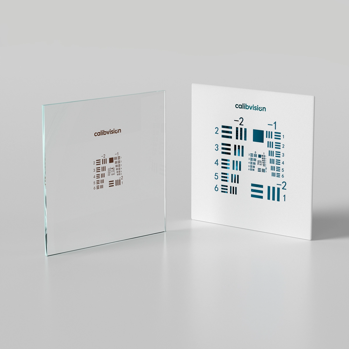
Chrome on soda-lime glass (brown chrome) — the standard choice: clean, durable, low-reflectivity, with a line-edge tolerance around ±50 nm, good through roughly Group 8.
Chrome on quartz glass (blue chrome) — for the finest groups and UV work: a tighter ±20 nm line tolerance, required for accurate measurement toward Group 9 Element 3 (912.30 lp/mm), and UV-transmissive.
Film — lower cost for large formats and less demanding resolution, at looser tolerance.
Printed / PDF — fine for demos and coarse checks only; ink edges and paper instability cap it at low groups (see USAF 1951 chart PDF & printable).
Every Calibvision USAF 1951 target ships with a serial-numbered inspection report; measurements are NIST/NIM-traceable, with product-level traceability under CNAS L0579 and recognised internationally through ILAC-MRA, and an accredited third-party calibration certificate is available on request.
By Size and Resolution Range
- High-Resolution: For testing microscopes and precision optics (Groups 4-9)
- Standard: For general optical testing (Groups 0-5)
- Low-Resolution: For testing wide-angle or low-magnification systems (Groups -2 to 3)
By Pattern Variation
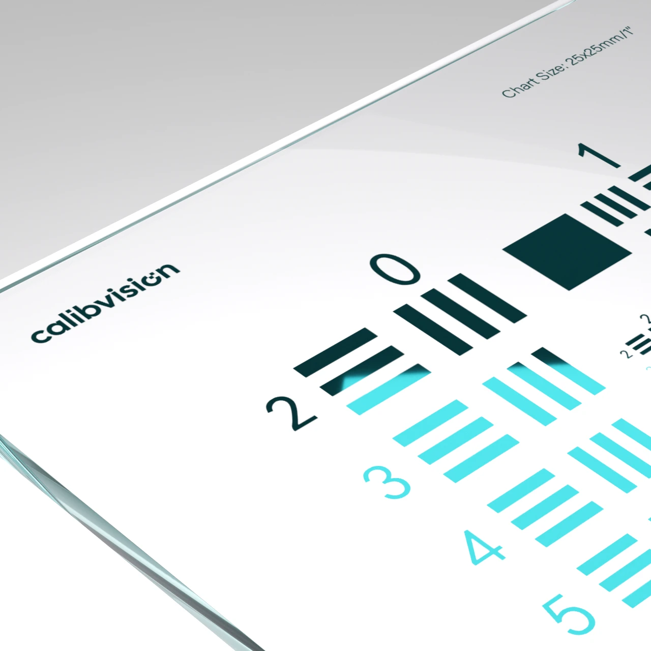
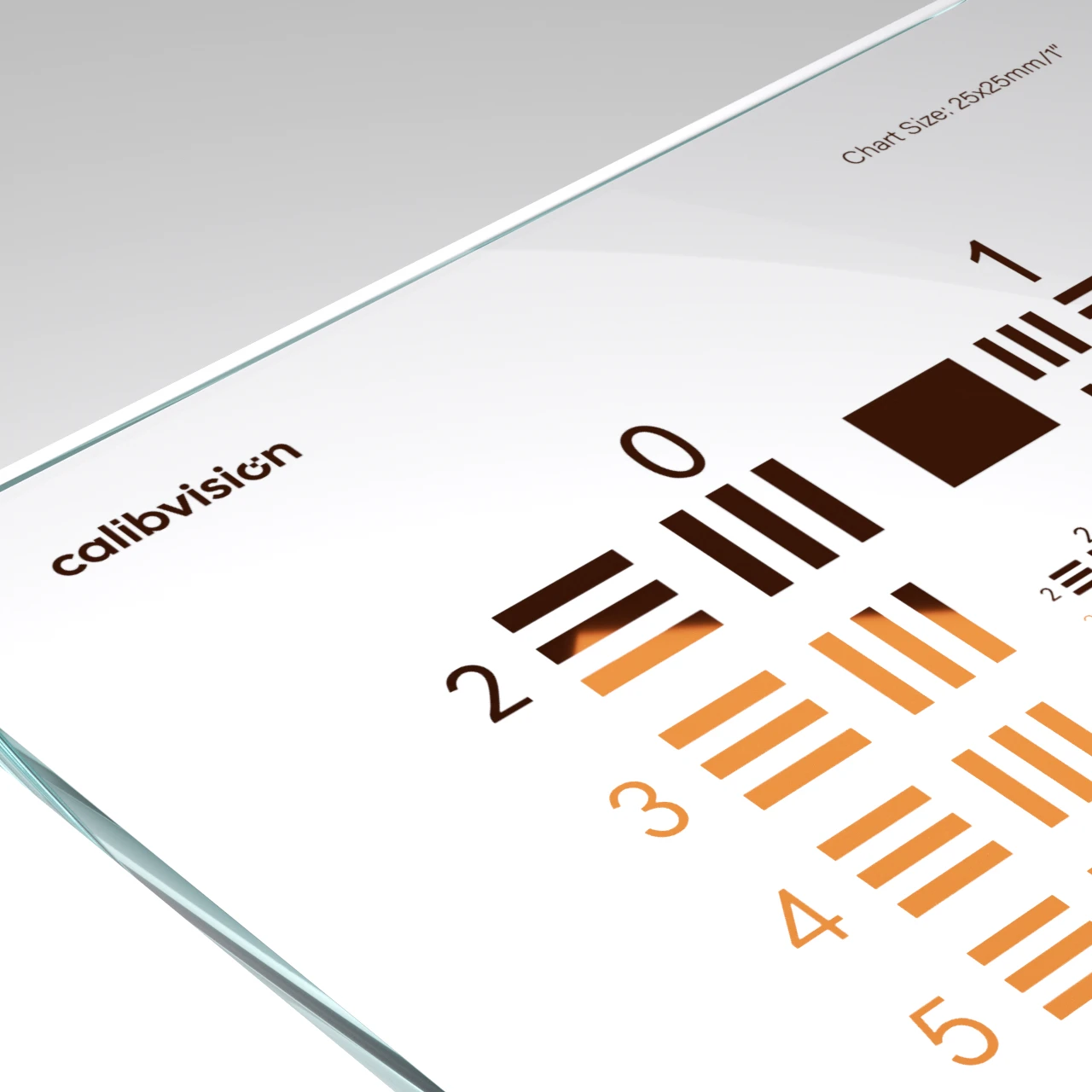
- Positive: Black lines on transparent/white background
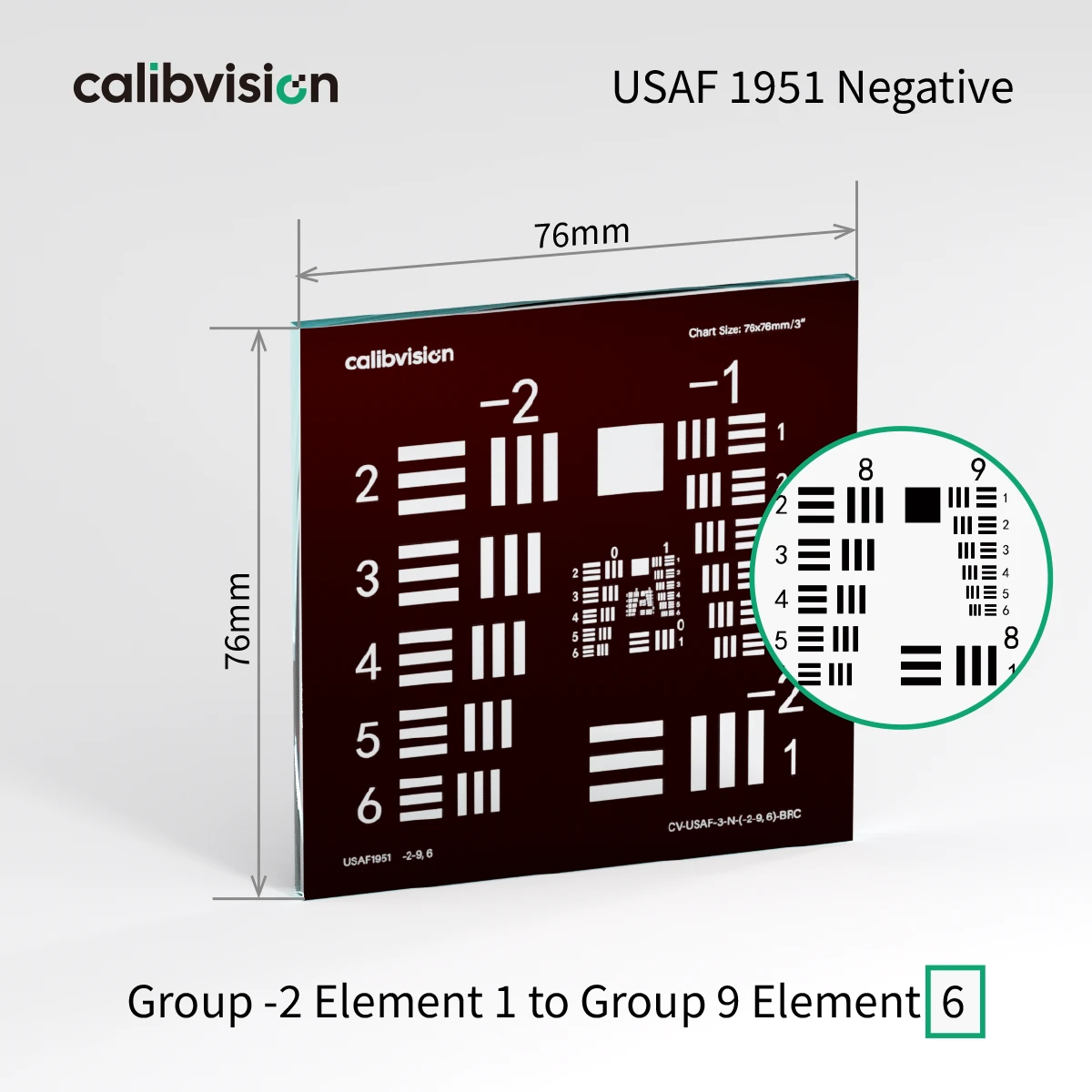
- Negative: Transparent/white lines on black background
- Hi-Contrast: Enhanced contrast for specialized applications
Reference Table for Group and Element Resolution
To simplify resolution determination, here’s a reference table of line pairs per millimeter for common group/element combinations:
| Group | Element 1 | Element 2 | Element 3 | Element 4 | Element 5 | Element 6 |
|---|---|---|---|---|---|---|
| -2 | 0.250 | 0.281 | 0.315 | 0.354 | 0.397 | 0.445 |
| -1 | 0.500 | 0.561 | 0.630 | 0.707 | 0.794 | 0.891 |
| 0 | 1.00 | 1.12 | 1.26 | 1.41 | 1.59 | 1.78 |
| 1 | 2.00 | 2.24 | 2.52 | 2.83 | 3.17 | 3.56 |
| 2 | 4.00 | 4.49 | 5.04 | 5.66 | 6.35 | 7.13 |
| 3 | 8.00 | 8.98 | 10.1 | 11.3 | 12.7 | 14.3 |
| 4 | 16.0 | 18.0 | 20.2 | 22.6 | 25.4 | 28.5 |
| 5 | 32.0 | 35.9 | 40.3 | 45.3 | 50.8 | 57.0 |
| 6 | 64.0 | 71.8 | 80.6 | 90.5 | 102 | 114 |
| 7 | 128 | 144 | 161 | 181 | 203 | 228 |
This table shows the resolution in line pairs per millimeter for each element in each group. Higher numbers indicate finer resolution capabilities.
Applications in Modern Technology
The USAF1951 test target remains relevant across numerous industries:
Machine Vision
In automated inspection systems, resolution determines the smallest defects that can be detected. Using the USAF1951 target helps engineers validate whether an optical system can detect features of the required size.
Medical Imaging
From microscopes to endoscopes, medical devices rely on precise optical resolution. The USAF1951 pattern helps ensure these systems meet the standards necessary for accurate diagnoses.
Smartphone Camera Development
Even consumer electronics manufacturers use USAF1951 targets (or derivatives) when developing and testing smartphone cameras. This helps engineers evaluate lens quality and sensor performance.
Scientific Research
In fields ranging from astronomy to biology, researchers use this standard to calibrate their imaging equipment and ensure consistent results.
Practical Tips for Using USAF1951 Test Targets
To get the most accurate results when testing with a USAF1951 chart:
- Control Your Lighting: Uneven illumination can skew results. Use diffuse, even lighting for the most accurate measurements.
- Maintain Proper Orientation: Mount the target perpendicular to the optical axis to avoid perspective distortion.
- Consider Working Distance: Test at the same distance your system will operate in real-world conditions.
- Check Both Axes: Always evaluate both horizontal and vertical resolution, as some optical systems may perform differently in each direction.
- Use Multiple Measurements: Take readings from different parts of the image field, especially when testing wide-angle lenses that might show varying resolution across the field.
- Ensure Proper Focus: Poor focus can dramatically affect resolution measurements. Take multiple measurements at slightly different focus positions to find the optimal setting.
- Control Contrast: Resolution measurements are only valid when sufficient contrast is maintained. Ensure proper exposure and lighting to achieve clear black and white patterns.
Converting Resolution to Practical Applications
Understanding what your measured resolution means in practice:
- For machine vision systems: If your system resolves 10 line pairs per mm, it can detect features as small as 50 micrometers (½ of the line pair period of 100 micrometers)
- For microscopy: Resolution can be converted to effective magnification
- For printing and scanning: Resolution can be related to DPI (dots per inch) by: DPI = line pairs per mm × 25.4
See our guide to testing microscope objective quality with USAF 1951.
Limitations of the USAF1951 Test Target
While incredibly useful, the USAF1951 target isn’t perfect:
- It primarily measures resolution but doesn’t fully characterize other optical qualities like distortion or chromatic aberration
- The discrete steps between elements mean you can’t get infinitely precise measurements
- The square-wave pattern doesn’t perfectly match the MTF (Modulation Transfer Function) approach used in modern optical design
For these reasons, some applications supplement USAF1951 testing with other methods like Siemens stars, slanted edge tests, or specialized software analysis.
Choosing the Right USAF1951 Test Target
When selecting a USAF1951 test target for your application, consider:
- Resolution Range: Ensure the target includes groups appropriate for your expected resolution. If you’re testing a microscope objective, you’ll need higher groups than if you’re testing a CCTV lens.
- Physical Size: Match the target size to your system’s field of view. Testing a wide-angle security camera requires a larger target than testing a macro lens.
- Construction Quality: Chrome-on-glass targets offer the highest precision but at a higher cost. For less demanding applications, printed targets may suffice.
- Positive vs. Negative: Some systems perform better with one pattern type than the other. If possible, test with both to get the most complete assessment.
Integration with Automated Testing Systems
Modern quality control often requires automated testing. The USAF1951 pattern works well with image processing software to provide objective, repeatable measurements.
A typical automated test workflow might include:
- Capturing an image of the test target
- Processing the image to detect the pattern elements
- Analyzing contrast levels between lines and spaces
- Determining the smallest resolvable element
- Calculating resolution in line pairs per millimeter
- Comparing results against specification requirements
- Automatically accepting or rejecting the tested component
Conclusion: A Time-Tested Standard
Few technical standards have demonstrated the staying power of the USAF1951 test target. What began as a military specification has evolved into a universal tool used across countless industries.
Its elegance lies in its simplicity – a pattern of lines that becomes progressively smaller in a predictable mathematical sequence. This simplicity makes it accessible to everyone from hobbyists testing vintage lenses to engineers developing cutting-edge machine vision systems.
Whether you’re calibrating a new optical system, comparing lens performance, or troubleshooting resolution issues, the USAF1951 test target provides a reliable, standardized method to quantify what your system can actually see.
Related Products You May Like
CalibVision manufactures USAF 1951 resolution test targets in chrome on glass — positive and negative, from Group 0 down to 0.55 µm line width (912.30 lp/mm), MIL-STD-150A compliant, on soda-lime or quartz glass — each with a serial-numbered inspection report and optional accredited third-party calibration. See specifications and request a quote.