Autonomous vehicle LiDAR testing is fundamentally different from generic LiDAR characterization. The reflectance target requirements escalate at every stage — research validation needs basic 10/50/90 multi-zone targets, OEM acceptance testing requires traceable metrology certification with sub-5% stress targets, and full production qualification involves multi-condition test programs spanning weeks of lab and outdoor work. Getting any stage wrong delays the entire vehicle program by months and costs millions in retesting.
This guide walks through the AV LiDAR testing pipeline as it actually operates inside automotive Tier 1 suppliers and OEM programs in 2026. We’ll cover the SAE automation level framework, the ISO standards that govern AV LiDAR validation, what test protocols look like at each development stage, and the specific reflectance target requirements that separate defensible test programs from those that fail OEM scrutiny.
I’ve worked with LiDAR engineers at automotive Tier 1 suppliers and OEM perception teams to spec test targets at CalibVision; the patterns below come from real test program requirements.
What Are the Different Levels of Autonomous Vehicle LiDAR Testing?
AV LiDAR testing is structured in stages that match the SAE automation level framework. Each stage has different objectives, test requirements, and reflectance target specifications:
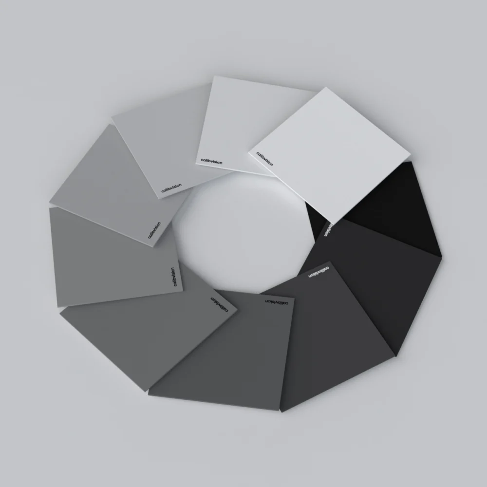
Research and development validation (SAE Level 0-2 features and early Level 3-4 development). Engineering teams characterize new sensors, validate perception algorithms, and identify failure modes. Test programs use multi-zone reflectance targets at 10/50/90 standard values, plus custom configurations as research questions arise. Documentation is internal — typically engineering reports, not formal regulatory deliverables. Target costs are moderate; test methodology is exploratory.
Pre-production qualification (preparing for OEM acceptance). Tier 1 LiDAR suppliers prove their sensor meets the OEM’s specified test conditions. Reflectance target requirements expand significantly: 10/50/90 standard, plus 5% stress and 95% saturation, all with traceable metrology certification. Multi-temperature characterization (typically 10°C, 20°C, 35°C). Outdoor weatherproof targets at the OEM’s test track. Documentation is formalized — calibration certificates with bilingual capability, traceability to national metrology institutes, and acceptance test protocol records.
OEM acceptance testing (Tier 1 → OEM handoff). The OEM verifies the supplier’s claims against their own test infrastructure. Same target specifications as pre-production qualification, but the OEM brings their own measurement equipment and runs the tests independently. The supplier provides target details and specifications but the OEM’s metrology lab confirms results. Documentation requirements are exhaustive — every measurement traceable, every condition logged.
Production qualification (PPAP — Production Part Approval Process). Sensor production lines are qualified to ship in volume. Acceptance testing happens on every production unit (or statistical samples) using simplified protocols — typically 50% reflectance only, at fixed lab distance, characterizing detection probability and intensity output. Production-line testing optimizes for speed (under 30 minutes per sensor) while maintaining defensible quality data.
Field deployment monitoring. Sensors deployed on production vehicles are continuously characterized through self-diagnostics rather than reflectance target testing. However, periodic recertification at OEM service centers may use reference targets to verify drift hasn’t compromised sensor performance.
The reflectance target investment scales roughly with stage progression: research uses 1-3 standard targets; pre-production needs 5-10 targets including custom; OEM acceptance and PPAP use comprehensive multi-target arrays with full traceability documentation.
What Standards Govern Autonomous Vehicle LiDAR Testing?
Three international standards frameworks define the testing requirements:
ISO 26262 (Functional Safety for Road Vehicles). Originally written for automotive electrical/electronic systems, ISO 26262 covers the LiDAR sensor’s functional safety — handling internal sensor failures (laser failure, detector degradation, electronics fault) without producing dangerous behavior. ASIL classification (A through D) defines the safety level required; most AV LiDAR aims for ASIL-B or ASIL-D depending on the perception system role. Test protocols include fault injection and diagnostic coverage testing.
ISO 21448 (Safety of the Intended Functionality / SOTIF). Specifically targets perception system safety where sensor function is correct but the system fails in environmental conditions outside its design envelope. SOTIF testing characterizes detection failures at low-reflectance edge cases (e.g., black vehicles in fog), saturation issues with high-reflectance bright surfaces, and adverse weather degradation. Reflectance target test programs are central to SOTIF validation — sub-5% reflectance stress tests and 95%+ saturation tests are SOTIF requirements.
UN-R157 (UNECE regulation for Automated Lane Keeping Systems). Specifies autonomous driving system performance requirements for vehicles regulated in Europe. Includes LiDAR detection range requirements at specified reflectance values and weather conditions. Test programs for vehicles intended for European certification must meet R157 minimum performance specifications.
Beyond these international standards, individual OEMs maintain proprietary testing protocols that often exceed minimum standard requirements:
- Tesla: AI-driven validation supplemented by physical sensor testing
- Waymo: Comprehensive multi-condition test protocols including weather and lighting variability
- Mercedes-Benz, Volvo, Polestar: OEM-specific acceptance protocols for Luminar 1550nm LiDAR integration
- BMW: Internal testing protocols leveraging Mobileye technology integration
- Toyota / Honda: Established test methodologies for ADAS feature progression
Each OEM’s specific protocol affects what reflectance target configurations a Tier 1 supplier needs to deliver.
For automotive Tier 1 suppliers building for OEM acceptance, the reflectance target supplier (CalibVision included) provides documentation that maps to specific OEM requirements. Bilingual (English/Chinese) calibration certificates, NIST-traceable / CMA-accredited / CNAS-aligned metrology certification, and detailed measurement uncertainty documentation are the typical deliverables.
What Reflectance Values Do Autonomous Vehicle Tests Require?
The 10/50/90 standard trio is the practical minimum for AV LiDAR testing, but OEM-grade programs expand significantly:
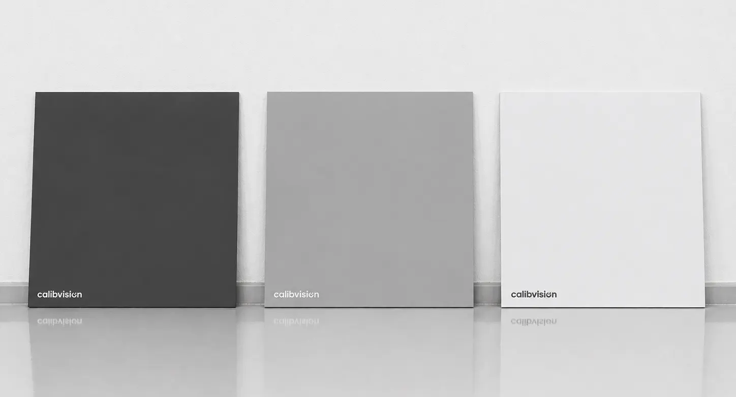
10% reflectance — worst-case detection. The metric most critical for AV safety. 10% targets stress-test detection of dark vehicles, dark pedestrians, fresh asphalt, and wet roads. AV LiDAR specifications typically reference 10% reflectance — “max range 200m at 10% reflectance” is the meaningful capability metric.
50% reflectance — typical-case characterization. Characterizes nominal detection accuracy and intensity calibration. 50% maps to typical scene materials (concrete, vegetation, mid-tone vehicle paint) the AV will encounter most of the time.
90% reflectance — saturation and high-albedo behavior. Tests sensor handling of bright surfaces (white vehicles, road markings, snow). Critical for verifying intensity dynamic range and characterizing close-range saturation effects.
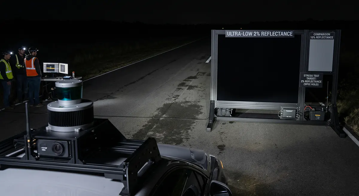
5% reflectance — SOTIFstress testing. Required for ISO 21448 SOTIF compliance. Reveals perception failure modes at the dark end of the operational envelope. AV systems must demonstrate detection performance at 5% reflectance to qualify for safety certification.
95% reflectance — saturationstress testing. Required for full saturation characterization, particularly at close range (5-15m from sensor) where bright surface returns can saturate detector electronics.
Sub-5% values for advanced edge-case testing. Some OEM programs require characterization at 2% and even sub-1% reflectance for absolute worst-case scenarios (light-absorbing dark cargo, deep shadows, extreme low-albedo conditions). These specialty targets are quoted on a custom basis.
A typical AV-grade reflectance target portfolio for a Tier 1 supplier looks like:
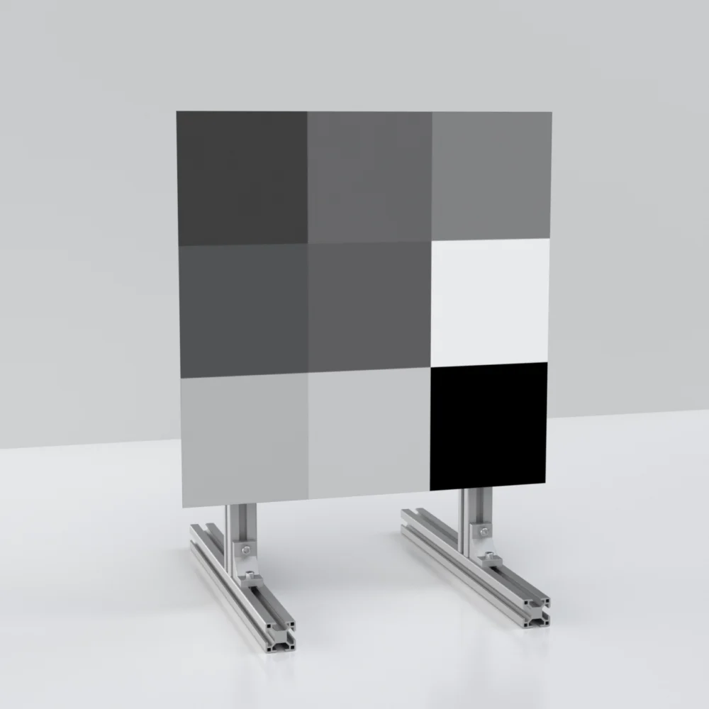
- Standard 18″×36″ multi-zone board with 10/50/90 zones (research and routine work)
- Custom 24″×48″ multi-zone board with 5/10/30/50/70/90/95 zones (comprehensive characterization)
- Custom 1.5m × 1.5m or larger board for outdoor long-range testing
- Sub-5% stress test panels (typically 2% and 5% values)
- Sintered PTFE 99% reference (for absolute reflectance calibration)
This portfolio investment runs $20K-$80K depending on size and certification level — a meaningful but justified expense for production-qualification programs.
How Does Multi-Sensor Fusion Affect AV LiDAR Testing?
Modern AV systems combine LiDAR with camera, radar, GPS, and IMU data into a single perception output. LiDAR testing must account for this fusion architecture:
LiDAR alone vs. fused output testing. Pure LiDAR detection range characterization (against multi-reflectance targets) measures the sensor’s raw capability. Fused-output testing measures the perception system’s overall performance — sometimes better than LiDAR alone (when camera and LiDAR confirm each other) and sometimes worse (when perception logic errs in handling sensor disagreement). Both types of testing are needed; reflectance target tests cover the first.
Radar/LiDAR cross-validation. Some perception architectures cross-validate radar and LiDAR detections to reduce false positives. Test programs may include scenarios where LiDAR detects a target but radar doesn’t (low-radar-cross-section targets) or vice versa (radar detects but LiDAR doesn’t, e.g., metal surfaces angled away from LiDAR but reflecting radar). Multi-reflectance target characterization establishes LiDAR’s role in this cross-validation.
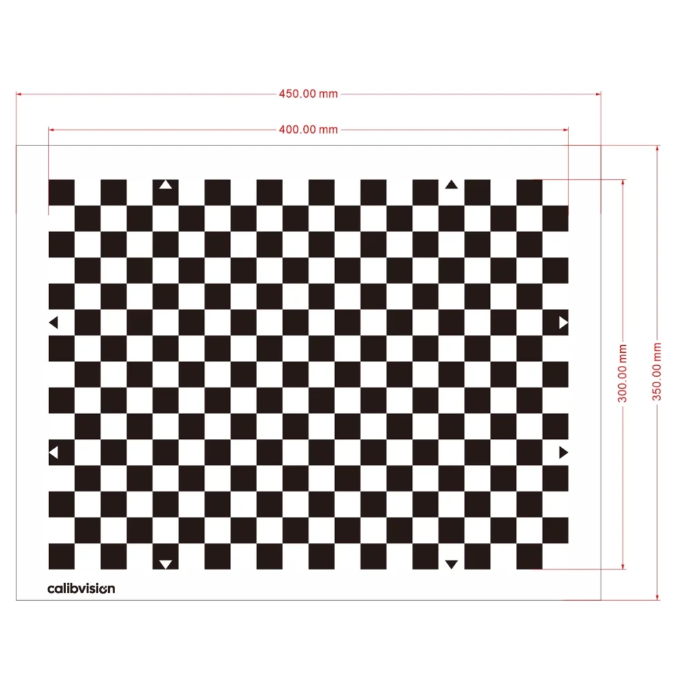
Camera/LiDAR alignment testing. Calibration between camera and LiDAR is itself a complex test domain. Reflectance targets serve dual purposes here — characterizing LiDAR independently while also providing visible reference points for camera calibration. Combination targets (high-reflectance with embedded fiducials) are sometimes used for joint calibration workflows.
Production vehicle integration testing. Once LiDAR is mounted in a vehicle, testing happens in the vehicle environment — reflectance targets at controlled distances on test tracks, in lab simulators, or via hardware-in-the-loop systems. Custom large-format reflectance targets (2m × 3m or larger) are typical for these integration test setups.
The multi-sensor fusion context means AV LiDAR test specifications often exceed pure-sensor characterization requirements — additional test conditions, broader reflectance value coverage, and integration-specific target configurations.
What Test Conditions Must AV LiDAR Pass?
Beyond standard lab characterization at 20°C clear conditions, AV LiDAR test programs include:
Multi-temperature operation. Sensors must perform across automotive operating temperature range — typically -20°C to +60°C. Test programs characterize detection range, range accuracy, and intensity calibration at temperature extremes. Reflectance targets must remain dimensionally stable and reflectance-stable across this temperature range.
Adverse weather conditions. Rain (specified rates: light 1mm/hr, moderate 5mm/hr, heavy 25mm/hr), fog (specified visibility: 50m, 100m, 200m), and snow (specified rates and accumulation). Outdoor weatherproof reflectance targets at controlled test track conditions characterize weather-driven detection range degradation.
Solar illumination effects. Direct sunlight at various angles tests detector saturation and noise floor degradation. Test programs include morning low-angle sun, midday high-angle sun, and sunset specific tests. Outdoor test track configurations with reflectance targets in known sunlight conditions characterize this.
Vibration and mechanical stress. Vehicle-mounted sensors experience continuous vibration. Acceptance testing includes detection range characterization during vibration, characterizing whether mechanical motion affects measurement quality. Vibration test setups use reflectance targets at fixed positions with the sensor on a vibration platform.
Long-duration operation. AV LiDAR must operate continuously for extended periods (hours of vehicle operation, fleet operation across days/weeks). Long-duration testing characterizes sensor drift, calibration stability, and any performance degradation over extended runtime. Multi-reflectance targets at fixed distances enable this characterization.
Fault injection. Functional safety testing (ISO 26262) requires demonstrating sensor behavior under fault conditions — laser power degradation, detector partial failure, electronics interference. Fault injection tests use reflectance targets to verify the sensor’s diagnostic outputs correctly identify the fault.
A complete AV LiDAR test program may span 200-500 hours of structured testing across multiple test facilities (lab, indoor track, outdoor test track, weather chamber) — orders of magnitude more comprehensive than research-grade characterization.
How Do You Specify Reflectance Targets for an OEM Acceptance Test Program?
When specifying reflectance targets for OEM acceptance testing, the deliverable list typically includes:
1. Multi-zone primary targets at the OEM‘s specified reflectance values. Most OEMs specify 5/10/50/90/95 as a 5-zone configuration on a single board, or 10/30/50/70/90 for finer characterization. Size depends on test distances — typically 24″×48″ for indoor lab work, custom 1.5m × 1.5m for outdoor track work.
2. Stress test targets (sub-5% and 95%+). Single-zone panels at very low (2%) or very high (95-99% sintered PTFE) reflectance. Characterized at the AV LiDAR’s wavelength (905nm or 1550nm depending on sensor type). Used for SOTIF-specific edge-case characterization.
3. Custom mounting configurations. Mount hole patterns matched to the OEM’s test fixture system. Allows direct attachment to existing test rigs without intermediate brackets that introduce alignment uncertainty. Documented with engineering drawings included in the order specification.
4. Outdoor weatherproof variants. For test track installations exposed to weather, weatherproof coating maintains reflectance values through 2-3 years of outdoor exposure. Substrate is honeycomb composite for ≤1mm flatness across the panel.
5. Calibration and traceability documentation. Per-target reflectance measurement at the specified wavelength under D50/2° illumination. Bilingual (English/Chinese) calibration certificate. Traceable measurement methodology with documented uncertainty. CMA-accredited and CNAS-aligned metrology institute submission for OEM acceptance.
6. Spare/replacement units. Production-grade AV programs require redundancy. Typical OEM acceptance specifications include 2-3 identical units of each target — primary, backup, and replacement. Spare units use the same calibration and certification as primary, ready for swap if a primary unit is damaged.
7. Documentation for OEM audit. Materials traceability, manufacturing process documentation, supplier certifications (ISO 9001 quality system, IATF 16949 automotive supplier qualification where applicable). The OEM may audit these documents as part of supplier qualification.
A typical OEM acceptance reflectance target deliverable for a Tier 1 LiDAR supplier runs $30K-$150K total, depending on size, certification level, and quantity. Lead time is 8-16 weeks for fully traceable certification.
What Mistakes Cause AV LiDAR Test Programs to Fail OEM Scrutiny?
Five mistakes consistently surface in OEM acceptance audits:
Targets without traceable calibration. OEM audit requires every reflectance value be traceable to a national metrology institute. Targets calibrated only by the manufacturer’s internal QC process (not externally verified) can fail audit even if the actual measurement is correct. Always specify CMA-accredited or NIST-traceable certification for OEM acceptance work.
Cross-wavelength target reuse. Using a 905nm-calibrated target on a 1550nm sensor (or vice versa) produces systematically wrong test data that can pass internal review but fail OEM verification. Match targets to sensor wavelength specifically; don’t interpolate.
Insufficient reflectance value coverage. Testing only at 10/50/90 misses SOTIF-relevant edge cases at sub-5% and 95%+. OEM SOTIF audit may require demonstrating performance across the full operational envelope; if test data only covers the standard trio, the program needs retesting with broader coverage.
Inadequate environmental documentation. Test conditions (temperature, humidity, ambient lighting, atmospheric conditions) must be logged with each measurement. Test programs that captured measurements without environmental documentation may need full re-testing if questioned during audit.
Specification ambiguity. Test data documentation must specify test reflectance, test distance, detection probability threshold, frame counts, and sensor configuration. Specifications that lack this detail create ambiguity that compounds during multi-stakeholder review and may require re-testing to resolve.
The cost of doing AV LiDAR testing wrong isn’t just bad data — it’s program delay. A retest cycle for a Tier 1 supplier can cost $500K-$2M and add 3-6 months to vehicle development. Investing properly upfront in target specification, calibration, and documentation pays back many times over.
What Documentation Does an AV LiDAR Test Program Need?
A defensible AV LiDAR test program produces documentation in three categories:
Technical specifications:
- Reflectance target serial numbers, calibration dates, measured reflectance values per zone
- Sensor model, serial number, firmware version under test
- Test environment conditions (temperature, humidity, ambient lighting, time of day)
- Measurement equipment used (laser rangefinders, environmental monitors)
- Test protocol followed (referenced to ISO 21448, ISO 26262, OEM-specific protocol)
Measurement records:
- Per-measurement raw data (point cloud captures, frame counts, timestamps)
- Computed metrics (detection probability, range bias, range precision, intensity output, ratios)
- Statistical analysis (means, standard deviations, confidence intervals)
- Anomaly logs (any unusual events during test sessions)
Compliance and audit records:
- Calibration traceability documentation (linked to national metrology institute)
- Quality management system records (ISO 9001 / IATF 16949 procedures followed)
- Test protocol approvals (review and sign-off from technical authorities)
- Audit trail for any test re-runs or specification changes
- Engineering change documentation if specifications evolved during the program
The total documentation volume for a complete AV LiDAR characterization at OEM acceptance level typically spans 500-2000 pages across these categories. This documentation is what makes test results defensible — both internally to engineering review and externally to OEM, regulatory, and certification audits.
FAQs
What’s the most common reflectance target configuration for AV LiDAR research?
A multi-zone 18″×36″ or 24″×48″ panel with 10%, 50%, and 90% Lambertian zones is the standard starting point for AV LiDAR research and engineering characterization. This covers the majority of research questions; custom configurations (5-zone gradient, sub-5% stress, custom mount holes) are added as specific research needs arise.
Do I need NIST or CMA traceability for AV LiDAR research?
For internal research and engineering work, manufacturer-provided calibration is typically sufficient. For pre-production qualification and OEM acceptance testing, traceable certification is required. CMA-accredited (China Metrology Accreditation) and CNAS-aligned (China National Accreditation Service for Conformity Assessment) certification are widely accepted by OEMs alongside NIST traceability for international acceptance work.
How long does an AV LiDAR test program take?
Research-grade characterization: 2-4 weeks. Pre-production qualification: 8-16 weeks. OEM acceptance testing: 12-24 weeks. Production qualification: ongoing with each production unit. Total elapsed time from initial sensor characterization to vehicle production qualification typically spans 12-24 months.
What’s the difference between AV LiDAR testing for SAE Level 2 vs Level 4?
Level 2 ADAS features (lane keeping, adaptive cruise) require detection performance at specified ranges in good conditions — usually 100-150m clear weather. Level 4 fully autonomous operation requires far broader test coverage: detection at extreme reflectance values (sub-5%, 95%+), adverse weather operation, multi-temperature qualification, fault injection testing, and full SOTIF compliance. Test program scope for Level 4 typically 5-10× the scope of Level 2.
Are reflectance targets reusable across different sensor models?
If the wavelength is the same, yes. A 905nm-calibrated multi-zone target works identically for any 905nm sensor. For OEM acceptance work spanning multiple sensor models, the same reflectance targets serve all sensors. For wavelength changes (e.g., a Tier 1 testing both 905nm and 1550nm sensors), separate targets calibrated at each wavelength are needed.
What target sizes work for outdoor test track AV LiDAR characterization?
Outdoor test track work typically uses targets at 1.5m × 1.5m or larger. For 905nm AV LiDAR characterized at distances under 200m, 1.5m × 1.5m to 2m × 2m is standard. For 1550nm long-range LiDAR characterized at 250m+, 2m × 3m to 3m × 5m custom configurations are typical.
Can I get AV LiDAR test targets with bilingual calibration certificates?
Yes. CalibVision provides bilingual (English/Chinese) calibration certificates suitable for international AV programs. The bilingual format is increasingly important as Chinese AV companies (Pony.ai, AutoX, WeRide, Baidu Apollo, Hesai LiDAR, RoboSense) interact with Western OEM customers, and as international AV programs source from globalized supply chains.
How does a reflectance target manufacturer support OEM acceptance testing?
Beyond delivering calibrated targets, the manufacturer provides supporting documentation needed for OEM audit: per-target measurement reports with traceable methodology, materials traceability records, manufacturing process documentation, and quality management system certificates. For long-running OEM programs, the manufacturer may also provide on-site technical support during acceptance test sessions and rapid replacement of any target damaged during testing. CalibVision provides this level of support for AV LiDAR programs as part of standard custom-order delivery.
Get AV LiDAR Test Targets from CalibVision
CalibVision manufactures the reflectance targets used in autonomous vehicle LiDAR test programs at scale — from research-grade multi-zone boards through OEM-acceptance-grade traceable configurations. Standard 18″×36″ and 24″×48″ multi-zone boards with 10/50/90 reflectance zones cover most research applications. For OEM acceptance testing, custom configurations with 5-zone or 7-zone gradient boards, sub-5% stress targets, sintered PTFE 99% references, custom mount holes drilled to your test fixture spec, weatherproof outdoor coating, and full traceability documentation are available.
Every target ships with per-panel calibration measurement at your specified wavelength (905nm, 1550nm, 940nm, or 850nm). For OEM-grade work, bilingual (English/Chinese) traceability certificates with CMA-accredited and CNAS-aligned metrology institute submission are available as optional add-ons.
Request a Custom Quote → | Browse 905nm Multi-Zone Targets → | Browse All Reflectance Standards →
What to Read Next
- The Complete Guide to LiDAR Reflectance Targets — main reference covering reflectance fundamentals across all LiDAR applications.
- How to Test LiDAR Performance with Reflectance Targets — step-by-step lab setup applicable to research-grade AV LiDAR characterization.
- LiDAR Detection Range vs Reflectance — Complete Physics Guide — physics fundamentals underlying AV LiDAR specifications and test methodology.
- 905nm LiDAR Reflectance Target — Selection & Testing Guide — wavelength-specific guidance for short-range AV ADAS sensors.
- 1550nm LiDAR Reflectance Target — Long-Range Automotive Testing — wavelength-specific guidance for long-range AV LiDAR sensors.
- Custom LiDAR Reflectance Targets — When Standard Sizes Aren’t Enough — guide to ordering custom configurations for AV programs.
References
- ISO 26262:2018. Road Vehicles — Functional Safety. International Organization for Standardization.
- ISO/PAS 21448:2019. Road Vehicles — Safety of the Intended Functionality (SOTIF). International Organization for Standardization.
- UN Regulation No. 157. Uniform Provisions Concerning the Approval of Vehicles with Regard to Automated Lane Keeping Systems. UNECE.
- SAE J3016:2021. Taxonomy and Definitions for Terms Related to Driving Automation Systems for On-Road Motor Vehicles. SAE International.
- IATF 16949:2016. Automotive Quality Management System. International Automotive Task Force.
- SAE International. SAE J3088: LIDAR Performance Specification (in development) — automotive LiDAR characterization standard.
- Industry analysis (2025-2026) — automotive Tier 1 LiDAR supplier acceptance test protocols and OEM acceptance documentation patterns.