905nm is the dominant LiDAR wavelength in 2026, powering most consumer-grade and automotive short-to-medium-range LiDAR systems on the market. Hesai, Velodyne, RoboSense, Innoviz Two, Ouster, and the LiDAR sensors in nearly every robotic vacuum, AGV, and warehouse automation system operate at 905nm. The reason is practical: silicon-based laser diodes at this wavelength are mature, low-cost, and high-volume — making 905nm the economical choice for any application that doesn’t strictly require the longer detection range that 1550nm enables.
For test labs characterizing 905nm LiDAR, the reflectance target choice matters more than most engineers realize. A target calibrated for visible light or for 1550nm gives systematically wrong reflectance values at 905nm, even when the difference looks small on a datasheet. This guide covers why 905nm dominates, who’s using it, how to size and select the right reflectance target, and the common pitfalls that invalidate 905nm test results.
Why Does 905nm Dominate Short-to-Medium-Range LiDAR?
Three factors made 905nm the default for production LiDAR:
Mature, low-cost laser diodes. 905nm sits in the near-infrared band where silicon-based vertical-cavity surface-emitting lasers (VCSELs) and edge-emitting laser diodes are produced in extreme volume for telecommunications, datacom, and consumer electronics. The supply chain is mature, costs are low, and reliability data is extensive. A 905nm laser diode costs a fraction of an equivalent 1550nm diode.
Silicon photodetectors are highly sensitive at 905nm. The silicon avalanche photodiodes (APDs) and single-photon avalanche diodes (SPADs) used in most LiDAR receivers have peak quantum efficiency in the 850-950nm range. At 905nm specifically, silicon detectors achieve 70-85% quantum efficiency — meaning most photons hitting the detector are converted to measurable signal. This is significantly higher than silicon’s response at 1550nm, where indium-gallium-arsenide (InGaAs) detectors are required.
Eye safety limits are workable for short-to-medium range. 905nm sits at the edge of the eye-safe wavelength region. Class 1 eye-safe operation at 905nm caps maximum laser power, which in turn caps maximum detection range — typically around 200m for production automotive LiDAR. For applications under 150-200m (most consumer, robotics, and industrial use cases), this isn’t a constraint.
The trade-off is that 905nm can’t reach the detection ranges that 1550nm achieves. Long-range automotive LiDAR (250m+) increasingly moves to 1550nm specifically to escape the 905nm eye-safety power cap. But for everything below that range threshold, 905nm remains dominant — and likely will for years.
The combination of factors that put 905nm at the top of LiDAR production volumes can be traced through the supply-chain stack:
[FIGURE 4 — 905nm Dominance Tree: see image brief below]
For a visual walkthrough of how a 905nm spinning LiDAR sensor actually works in real time, Velodyne’s official explainer video [How Does LiDAR Work?] provides a useful 5-minute overview.
Which LiDAR Systems Use 905nm?
A non-exhaustive list of 905nm LiDAR sensors in production as of 2026:
Automotive and ADAS LiDAR:
- Hesai (AT128, QT128, Pandar, XT family)
- Velodyne (Puck, Ultra Puck, Velarray families)
- RoboSense (Helios, RS-Bpearl, RS-LiDAR-M family)
- Innoviz Two
- Ouster (OS-0, OS-1, OS-2 — actually use 850-865nm but functionally similar to 905nm test work)
- Ibeo and Continental short-range automotive LiDAR
Robotics and AGV LiDAR:
- Most robotic vacuum LiDAR (Roborock, Ecovacs, iRobot Roomba — typically 905nm or close variants)
- AGV navigation LiDAR (Geek+, Quicktron, HikRobot, Mir Robotics)
- Warehouse and logistics robotics
- Agricultural autonomous vehicles
- Mobile inspection robots
Industrial and specialty:
- Production-line LiDAR for automated quality inspection
- Drone LiDAR for survey and mapping (most consumer drones use 905nm)
- Indoor 3D scanning for facility documentation
- Many academic and research LiDAR platforms
Consumer and prosumer:
- Apple iPhone Pro LiDAR (technically 940nm, but functionally adjacent)
- Some AR/VR depth sensors
- Robotics hobby and education platforms
The pattern: if your LiDAR is for short-to-medium range, automotive forward-sensing within 200m, robotics, or consumer applications — it’s almost certainly 905nm or in the 850-950nm band that test targets calibrated at 905nm cover effectively.
How Does 905nm Differ from 1550nm and 940nm?
Before getting into specific differences, it helps to see where these LiDAR wavelengths sit in the broader infrared spectrum. The infrared band stretches from 750 nm (just past visible red) to 15,000 nm, divided into four sub-bands: Near-infrared (NIR, 750-1400 nm), Shortwave infrared (SWIR, 1400-3000 nm), Mediumwave infrared (MWIR, 3000-8000 nm), and Longwave infrared (LWIR, 8000-15,000 nm) [Inertial Labs, 2024].
905 nm and 940 nm sit in the NIR band, where silicon-based detectors work efficiently. 1550 nm is in the SWIR band, where InGaAs detectors are required. The 1400 nm boundary between NIR and SWIR isn’t arbitrary — it’s where silicon’s photodetection efficiency drops below 1%, making the wavelength choice fundamentally a question of which detector technology can be used.
FIGURE 1 — Infrared Wavelength Spectrum: see image brief below
The four common LiDAR wavelengths have very different cost, performance, and detector technology profiles. The table below summarizes the key technical differences:
[TABLE 1 — see specification table below]
Two specific data points from this comparison deserve closer attention:
1550nm has approximately 40× higher eye-safety threshold than 905nm at the same laser output power. This is because 1550nm is absorbed in the cornea and lens before reaching the retina, while 905nm passes through the eye optics and focuses onto the retina — exactly where photoreceptor damage is most likely. The IEC 60825-1 maximum permissible exposure (MPE) for 905nm is in the millijoule range; for 1550nm, it’s in the tens of millijoules. This gap directly explains why long-range automotive LiDAR moves to 1550nm: more allowable laser power means more detection range without violating eye-safety regulations [Leishen, 2022; Inertial Labs, 2024].
1550nm produces a beam spot ~4× smaller than 905nm at 100m distance because of better beam collimation properties at the longer wavelength. This translates directly into higher angular resolution for object detection at long range [Leishen, 2022; Inertial Labs, 2024].
| Specification | 905nm | 940nm | 850nm | 1550nm |
| Spectrum Band | NIR | NIR | NIR | SWIR |
| Detector Type | Si APD/SPAD | Si APD/SPAD | Si APD/SPAD | InGaAs APD |
| Detector Quantum Efficiency | 70-85% | 65-80% | 70-85% | 70-90% |
| Component Cost (relative) | 1× (baseline) | 1.2× | 1× | 5-10× |
| Eye-Safety MPE (Class 1) | Reference | Similar to 905nm | Similar to 905nm | ~40× higher |
| Typical Max Detection Range | 150-200m | <5m (short-range) | 30-50m (indoor) | 250-400m+ |
| Beam Spot @ 100m (relative) | 4× | 4× | 4× | 1× |
| Atmospheric Penetration | Good | Good | Good | Better (dust/fog) |
| Rain/Snow Performance | Better | Better | Better | Worse |
| Heat Dissipation | Standard | Standard | Standard | Significant |
| Solar Background Noise | High | High | High | Moderate |
| Supply Chain Maturity | Highly mature | Highly mature | Mature | Maturing |
| Typical Applications | Auto ADAS, robotics, AGV | Consumer ToF (iPhone, AR/VR) | Indoor robots, security IR | Long-range AV (Luminar/Aurora) |
| Indicative System Cost (USD) | $500-$5K | $50-$500 | $200-$2K | $5K-$50K+ |
Luminar’s design lab series includes a detailed engineering explanation of why their automotive LiDAR uses 1550nm rather than 905nm — useful technical context for understanding the trade-offs.
905nm — silicon-based, short-to-medium range, eye-safety limited. Mature ecosystem, cheap components, strong silicon detector response. Maximum production-LiDAR range typically 200m. Dominates automotive forward-sensing under 150m, robotics, AGVs.
1550nm — InGaAs-based, long range, more eye-safe per watt. Eye-safety limits allow much higher laser power than 905nm, which translates to detection ranges above 250m. But components cost 5-10× more than 905nm, and InGaAs detectors are less mature than silicon. Used in long-range automotive LiDAR (Luminar, Aeva, Aurora, Innoviz Pro) where the extra range justifies the cost.
940nm — silicon-based, short range, consumer ToF focus. Closely related to 905nm physically, but optimized for consumer time-of-flight applications (iPhone, iPad, Vision Pro, AR/VR headsets). Maximum range typically under 5m. Calibrated reflectance values at 940nm are slightly different from 905nm — close enough to interpolate but not equivalent for precision work.
850nm — silicon-based, security and indoor IR. Slightly visible as a faint red glow if you look directly at the source. Used in security cameras with IR illumination, indoor robotics, and some legacy consumer ToF sensors. Detector response at 850nm is even higher than 905nm but eye-safety limits more restrictive.
Key cross-wavelength behavior: A target calibrated at 905nm typically reads within ±2-5% of the same value at 940nm and 850nm (because all three are in silicon’s response band). At 1550nm, the same target’s reflectance can shift by 10-30% — because 1550nm is in a different optical regime where many materials behave differently. Don’t use a 905nm-calibrated target to test 1550nm sensors. For tests at 850nm or 940nm with a 905nm-calibrated target, the error is small but exists; for precision work, order targets calibrated at the actual sensor wavelength.
What Reflectance Values Do You Need for 905nm Testing?
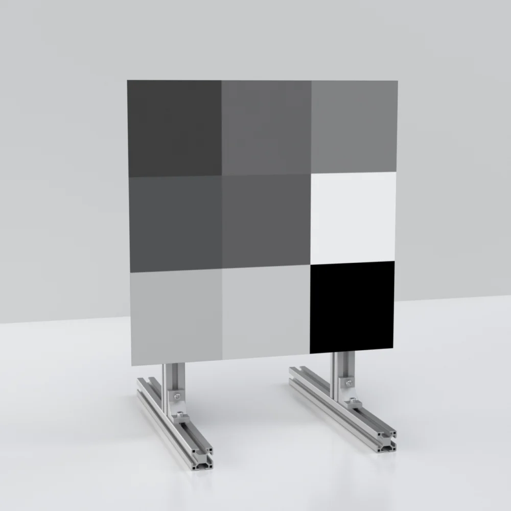
For 905nm LiDAR characterization, the standard 10%, 50%, 90% trio is the right starting point — same as for any LiDAR wavelength. Each value tests a different sensor behavior:
10% reflectance — stress-tests detection range against worst-case dark scenes. Black vehicles at night, fresh asphalt, dark clothing, wet road surfaces. The metric most often misrepresented in datasheets and most often surprising in field deployment.
50% reflectance — characterizes typical real-world performance against mid-tone surfaces (concrete, average paint, vegetation, building facades). This is the reference for nominal detection accuracy and intensity calibration.
90% reflectance — verifies behavior with bright surfaces and tests close-range saturation. White vehicles, road markings, snow, light surfaces. Modern 905nm LiDAR detects 90% targets at extreme range without difficulty — the test value is in characterizing saturation behavior, not detection range.
For 905nm specifically, two situations call for additional reflectance values:
Sub-10% values for automotive perception stress testing. Modern automotive LiDAR systems include 905nm in safety-critical perception pipelines. Stress testing these pipelines against 2-5% reflectance scenes (deep shadows, low-albedo dark vehicles in twilight) catches edge-case failure modes before deployment. Not strictly required for general characterization, but valuable for safety-certification testing.
95%+ values for production-line saturation testing. Production LiDAR sensors sometimes show saturation artifacts at very close range against bright targets — blooming, ghosting, false returns. Including a 95% target in production-line acceptance testing catches these failure modes.
For most 905nm applications, a 10/50/90 multi-zone target plus a separate 5% target (if doing safety-certification work) covers the full test program.
How Big Should Your 905nm Test Target Be?
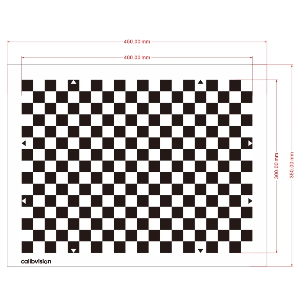
Target size depends on test distance and the LiDAR’s beam divergence. The general principle: the target should be at least 3× the LiDAR beam footprint diameter at the test distance. For 905nm production LiDAR with typical 0.1° to 0.3° beam divergence:
| Test Distance | Recommended Minimum Target Size |
| Up to 25m | 200 × 200mm |
| 25-50m | 300 × 300mm |
| 50-75m | 600 × 600mm (or 18″×36″ multi-zone) |
| 75-100m | 600 × 600mm to 1m × 1m |
| 100-150m | 1m × 1m or 24″×48″ multi-zone |
| 150-200m (905nm max) | 1.5m × 1.5m custom |
Two practical considerations specific to 905nm:
Consumer-grade and short-range robotics LiDAR has wider beam divergence. Robotic vacuum cleaners and indoor AGVs typically have 0.5° to 1° beam divergence — 3-10× wider than automotive sensors. For testing these systems at typical distances (5-15m), the 200×200mm to 400×400mm range is usually sufficient. Don’t over-spec target size for short-range sensors.
Most production-line acceptance testing happens at 25-50m. Standard 18″×36″ multi-zone targets work well for this distance range and are a common QC fixture configuration. For production-line work, the 600×600mm zone size is generous — even small alignment errors don’t compromise the measurement.
For long-range automotive 905nm (the 150-200m end of the wavelength’s useful range), custom-sized targets at 1.5×1.5m or larger are typical. Above 1.5m, honeycomb composite substrate is required to maintain ≤1mm flatness across the panel.
How Do You Set Up a 905nm Test Lab Environment?
Three environmental factors specifically affect 905nm test results:
Solar near-infrared contamination is significant at 905nm. The sun emits substantial radiation in the 800-1000nm band, which reaches Earth’s surface during daylight hours. Indoor labs with windows or skylights may have enough solar near-infrared leak to raise the 905nm noise floor by 10-20%. For precision testing, solar-blocking films on windows or testing during evening hours eliminates this. Outdoor 905nm testing is essentially impossible during peak daytime sun without active filtering.
Most LED and fluorescent lighting is acceptable at 905nm. Standard fluorescent tubes, white LED panels, and HID warehouse lighting emit minimal radiation at 905nm. These can stay on during testing without affecting results. Halogen and incandescent lighting do emit some 905nm and should be avoided in the test space.
Temperature affects 905nm laser diode performance. Most production 905nm LiDAR sensors include thermal management, but extreme lab temperature swings (above 35°C or below 5°C) shift the sensor’s output power and detection sensitivity. Lab temperature stable within ±2°C is the practical requirement for repeatable testing.
For longer test sessions (multi-hour characterization runs), record temperature alongside each measurement. This lets you flag any temperature-driven drift in test data and is required documentation for OEM acceptance testing.
What Test Setup Mistakes Are Common with 905nm?
Five mistakes that invalidate 905nm test results:
Using a target calibrated for visible light or 1550nm. A target with “98% reflectance” specified for visible light might reflect 75% at 905nm — and the test data based on that mismatch is wrong by 25%. Always verify the target is characterized at 905nm specifically, not interpolated from another wavelength.
Testing in mixed-lighting environments. A lab with overhead LED panels plus a window with afternoon sun has wildly varying 905nm noise floor through the day. Test sessions running over multiple hours produce inconsistent data without identifying why. Block solar leak or schedule tests during evening hours.
Not isolating the test path from secondary reflections. A LiDAR aimed at a target with a glossy painted wall behind it will get returns from both the target and the wall, contaminating the intensity measurement. Walls behind the target should be matte black or covered with anti-reflection foam during testing.
Confusing “905nm” with “near-infrared” generically. Some general-purpose IR materials are characterized only at “near-infrared” without specifying wavelength. These can shift 5-15% in reflectance between 850nm and 950nm, which is enough to invalidate precision measurements. Specifically verify the calibration wavelength.
Using outdoor reflectance values for indoor lab testing. Some materials show different reflectance under direct sunlight vs controlled lab illumination — usually because solar UV slowly degrades the surface. If your 905nm target has been used outdoors before lab testing, recalibrate before treating the published reflectance values as accurate.
These five mistakes account for most of the “my 905nm test data doesn’t make sense” calls we get from customers. All five are preventable with attention to source material certification and lab environment control.
What’s the Maximum Detection Range of 905nm LiDAR?
For Class 1 eye-safe production 905nm automotive LiDAR, maximum useful detection range is typically:
- 10% reflectance target: 100-200m (varies by sensor model)
- 50% reflectance target: 150-300m
- 90% reflectance target: 200-400m+
These ranges are theoretical maximums under ideal lab conditions. Real-world detection range in adverse weather, with solar interference, or against non-ideal surfaces is typically 30-60% of the lab number.
For comparison, 1550nm long-range automotive LiDAR achieves:
- 10% reflectance: 250-400m
- 50% reflectance: 400-600m
- 90% reflectance: 500-800m+
The ~2× range advantage of 1550nm comes from the higher allowed laser power under eye-safety regulations — the wavelength itself isn’t fundamentally better at long range. As 905nm laser technology improves and as eye-safety analysis methods get more sophisticated, some 905nm sensors are pushing toward 250m. But fundamentally, sub-200m is 905nm territory and 200m+ increasingly belongs to 1550nm.
For production LiDAR testing, the relevant question isn’t “what’s the absolute maximum range” but “what’s the detection probability at the distance my application requires.” That’s why every 905nm test program characterizes detection probability across distances rather than reporting a single “maximum range” number — and why 905nm reflectance targets calibrated at the wavelength are essential for getting honest answers.
Detection range for any LiDAR follows a fundamental physics relation known as the LiDAR range equation. For diffuse-target detection in the most common operational regime:
[FIGURE 3 — LiDAR Range Equation: see image brief below]
Simplified form:
R_max ∝ √(P_laser × ρ_target × A_aperture / NEP)where:
- R_max = maximum detection range
- P_laser = peak laser power
- ρ_target = target reflectance
- A_aperture = receiver aperture area
- NEP = receiver noise equivalent power
Two practical implications follow directly:
- Range scales with √P_laser, not linearly. Doubling laser power increases range by only ~1.4× (square root of 2). To double range, you need 4× the laser power. This is why eye-safety limits on 905nm cap maximum range so steeply — there’s no easy way to “just push more power.”
- Range scales with √ρ_target. A 10% reflectance target detects at ~33% the range of a 90% target (√(0.1)/√(0.9) ≈ 0.33). This explains the wide gap between datasheet “max range” claims (typically measured at 90% reflectance) and real-world performance against typical scenes.
The 40× eye-safety advantage of 1550nm over 905nm translates to √40 ≈ 6.3× theoretical range advantage. In practice, detector sensitivity differences (silicon at 905nm vs InGaAs at 1550nm) narrow the realized gap — but the physical advantage is real and substantial.
Why Is 1550nm “Safer for the Eye” Than 905nm at the Same Power?
The eye-safety advantage of 1550nm over 905nm comes down to where each wavelength is absorbed in the human eye. Wavelengths between 400 nm and 1400 nm pass through the cornea and lens and focus directly onto the retina. The retina contains the photoreceptor cells, which are damaged when local temperature rises by more than 10°C — and this damage is permanent because retinal cells don’t regenerate [Leishen LSLiDAR, 2022].
905 nm sits squarely inside this 400-1400 nm “retinal danger band.” A 905 nm laser pulse passes through the eye optics and concentrates all its energy onto a tiny retinal spot. Even a low-power 905 nm pulse can produce significant local heating because the focusing geometry multiplies the energy density by a factor of roughly 100,000 between the cornea and the retina.
1550 nm is absorbed in the cornea and lens before reaching the retina. This means a 1550 nm laser of the same power deposits its energy across a much larger area in the eye’s outer structures, which dissipate heat rapidly and have higher damage thresholds.
The simplified eye-safety equation explains the practical impact:
[FIGURE 2 — Eye-Safety Comparison Diagram: see image brief below]
The IEC 60825-1 international standard codifies these physical differences as different Maximum Permissible Exposure (MPE) limits for each wavelength. At equivalent geometric conditions:
MPE (1550nm) ≈ 40 × MPE (905nm)
This is the foundation of the “1550nm allows 40× higher laser power under Class 1 eye-safety” specification widely referenced in LiDAR literature [Leishen, 2022; Inertial Labs, 2024]. The detection-range advantage of 1550nm is a direct consequence: detection range scales with the square root of laser power for diffuse targets, so 40× higher allowable power translates to roughly 6× longer detection range — though in practice other factors limit the realized advantage to about 2× in production sensors.
For an academic-level explanation of laser eye safety physics and the IEC 60825-1 classification system, see [SPIE OPEC video on laser safety classification
FAQ
Is 905nm eye-safe?
905nm is in the Class 1 (eye-safe under all conditions of normal use) wavelength band when laser power is kept below specific limits defined by IEC 60825-1 and FDA regulations. Production automotive LiDAR systems are designed within these limits, which caps their maximum laser pulse energy and indirectly caps their maximum detection range. 905nm itself is not “more eye-safe” than 1550nm — both are eye-safe under their respective power limits — but 1550nm’s higher allowed power explains why long-range automotive LiDAR moved to 1550nm rather than pushing 905nm power limits.
Can I use a 905nm target with a 940nm LiDAR sensor?
For approximate testing, yes — 905nm and 940nm are in the same silicon detector response band, and most calibrated reflectance targets show reflectance values within ±2-5% between these wavelengths. For precision testing where this small difference matters, order targets specifically characterized at 940nm. The shift is most significant at the high-reflectance end (90% zone shows larger drift than 10% zone between wavelengths).
References
- Leishen LSLiDAR. (2022). 905nm vs 1550nm: Which Is Better for Automotive LiDAR? Retrieved from https://www.lslidar.com/905nm-vs-1550nm-which-is-better-for-automotive-lidar/
- Inertial Labs. (2024, December). Why Have 905 and 1550 nm Become the Standard for LiDARs? Retrieved from https://inertiallabs.com/why-have-905-and-1550-nm-become-the-standard-for-lidars/
- Erdi CN. (2024). Why Does LiDAR Use 905nm and 940nm Bands? Retrieved from https://erdicn.com/blogs/news/why-does-lidar-use-905nm-and-940nm-bands
- IEEE Xplore Document 8925087. LiDAR Wavelength Comparison. https://ieeexplore.ieee.org/document/8925087/
- Luminar Technologies. LiDAR Design Lab: Wavelength. https://www.luminartech.com/updates/lidar-design-lab-wavelength
- EE Times. (2023). What’s the Direction for Automotive LiDAR — 905nm or 1550nm? Retrieved from https://www.eetimes.com/whats-the-direction-for-automotive-lidar-905-nm-or-1550-nm/
- IEC 60825-1:2014. Safety of Laser Products — Part 1: Equipment Classification and Requirements.
What to Read Next
- The Complete Guide to LiDAR Reflectance Targets — main reference covering reflectance fundamentals, materials, and applications.
- 10%, 50%, and 90% Reflectance Targets — Which Do You Need? — deep-dive into reflectance value selection for 905nm and other wavelengths.
- How to Test LiDAR Performance with Reflectance Targets — step-by-step lab setup guide for 905nm and other wavelengths.
- Custom LiDAR Reflectance Targets — When Standard Sizes Aren’t Enough — for non-standard 905nm configurations.
- Lambertian vs Specular vs Retroreflective Targets — surface mode fundamentals for reflectance test work.